Monday, January 11, 2016

Project SSTC2 - Part 2 (Just a quick update - more to come)

Current issues that I'm addressing (to finish this coil).  I want to do it right so I'm trying not to rush it (even though I want to - just so I can have it done).
  • rewinding secondary coil (DONE)
    • My initial coil I ruined when I tried removing some inclusions trapped in the resin coat I applied - ended up pulling and breaking one winding.
    • Decided to completely rewind new coil (wanted it to look good)
      • made a winding rig and cut winding time in half
  • Question regarding capacitor on MOSFET gate drive chip in Guangyan's schematic
    • The datasheet for the UCC27425 and schematic differ.  Page 10 of the datasheet recommends 
      • "two VDD bypass capacitors are recommended to prevent noise problems. The use of surface mount components is highly recommended. A 0.1-μF ceramic capacitor should be located closest to the VDD to ground connection. In addition, a larger capacitor (such as 1-μF) with relatively low ESR should be connected in parallel, to help deliver the high current peaks to the load."
  • Primary Side of coil
    • voltage double (DONE)
      • difficulty finding capacitors that I could pull from older scrap
      • ended up breaking down and ordering them
    • Concerned about minimizing stray inductance in half bridge (DONE)
      • etching/making multi layer pcb (unable to)
      • make connections with copper sheet/plate
        • unable to solder to wider or thicker copper
          • heat conductivity of copper so high that entire area would need to be heated enough to melt and bond solder which would require higher temps for a longer period of time (would end up killing sensitive components).
      • compromised by using narrower copper sheet/plate
  • Want to get an actual measure of the resonant frequency of my secondary coil
    • Need to finish making a working Frequency/signal generator (DONE)
      • AD9850 working - set up to scan from 100kHz to 200kHz (as a start, each second frequency increases by 1kHz) - Yes I'll be posting an update to my AD9850 Signal Generator Project.
  • Finish making a nicer looking Topload for Secondary Coil
    • Not an immediate concern - I do have Topload's I can use for testing
  •  Make shielded enclosure for electronics
  • Add optical connection for external interrupter
    • Also not an immediate concern - more something to add after all is working reliably.
SSTC2 part 1

Project - Biofeedback EEG Mindflex to MindWaveMobile Headset

Converting a Mindflex to a MindWaveMobile Headset

This basically involves adding a Bluetooth serial transmitter (and configuring it) to the Mindflex Headset and changing some components on the TGAM1 board (the board that acquires the EEG data).

This ended up being a bit of an adventure – even after a good deal of research (reading datasheet's very carefully) and reviewing other peoples tutorials of similar hacks. In the end, it took about a week of part time research on components, Bluetooth (profiles, module boards, communication protocols), TGAM1 board (communication protocols, identifying board connection points, hardware settings etc.). Presently, I have a fully functional headset that is recognized by Neurosky's MindWaveMobile software as a MindWave Mobile Headset.

Hardware:

  • Mindflex Headset ($10-20 on ebay)
  • HC-06 Bluetooth Slave Module (that communicates with Serial Port Profile (SPP))
    • these are between $5-10 on Amazon or Ebay (cheaper in quantity, or if you are willing to wait, from China)
    • should be able to use an HC-05 also (connections and configurations a little different – HC-05 can be configured either as a Master or a Slave module – unlike HC-06 which is only one or the other)
    • I'm a noob concerning Bluetooth: protocols, host modes, etc.
  • 10k resistor (pull up to set TGAM board to 57600 baud, ¼ or 1/8 watt)
  • Hookup wire

Tools:

  • Soldering iron (and solder, of course)
  • Multi-Tester/VOMeter (non-essential - mainly to verify connections)
  • Magnifier (non-essential - to see TGAM1 board pins and labels clearly)
  • 5V to 3.3V Level Shifter (essential if using an Arduino board to set up the Bluetooth module, non-essential otherwise)
  • Some type of USB to TTL Serial Converter (for setting up Bluetooth module board)
    Some Options for Setting Up HC-06 Module
      • Only need 4 pins (Power, GND, TX, RX)
         
    • Adafruit's Console Cable - USB to TTL Serial Cable - Debug / Console Cable https://www.adafruit.com/product/954.There are four wires:
      • red (power)
      • black (GND)
      • white (RX) into USB port
      • green (TX) out of the USB port.
        • The power pin provides the 5V @ 500mA direct from the USB port and the RX/TX pins are 3.3V level for interfacing with the most common 3.3V logic level chipsets.
      • Initially, this is what I was using (at first it was working through a terminal program using serial communication – then it just stopped working. It turns out I need a newer chipset for it to work correctly on Windows 10)
         
    • BusPirate – this should work with no problem when combined with a terminal program (Teraterm, Putty, etc) in serial mode
       
    • Arduino Board with USB connection
      • Software Serial sketch
        • This is what I ended up using and it worked fine – though you do need to upload the sketch a few times:
          • Change baud rate of module
          • change software serial baud rate – reload
          • etc.

Here are a couple of screen shots of the headset working with a couple of applications:


 I'll post a full write up of this build soon.

Wednesday, January 6, 2016

Project Signal Generator: AD9850 DDS Board

I've been messing with an AD9850 DDS Board, on and off, for a while now.  Initially I thought I'd just be able to replicate some one else's project, like the following ones from Instructables:
But, for various reasons I couldn't get things to work how I wanted them to.  I also looked at different Arduino Libraries for the AD9850 and had problems understanding the different functions in the libraries and how to call them, etc. (primarily due to my beginner/noob skills in programming).  As a result,I decided to take a step back and go to a more basic and direct level and not use a Library but instead just write more direct code.

My first step is to really dig into the datasheet for the AD9850  - (this is the datasheet for the chip from Analog Devices).
Important Info from datasheet:
  • PSU to chip/board is 5V
  • logic levels are also 5V
  • Important Pins: (descriptions on p5 of the datasheet)
    • Vcc
    • GND
    • D7 - this is our serial data input pin
    • W-CLK - Word Load Clock (our clock pin for loading serial data) - when pulled high it loads next bit into register then pull low before starting over with next bit
    • FQUP - Frequency Update Pin (like a latch pin for a shift register) - pulled high then low to enable serial mode and again after filling register to load bits in to update frequency (not completely clear in datasheet)
    • RESET - Master Reset for board and registers on board (need to perform at start and possibly before each time frequency is updated/changed)
The Serial Enable and Load sequence is on p12 of the datasheet. Another important detail is the timing diagrams on p11 (list the minimum times between clock pulses, etc as well as the minimal pulse width's).

To set the frequency of the AD9850 we need to load a 40 bit word through the D7(serial data loading pin). This is summarized on page 9 of the datasheet: 32 bits set the frequency, 3 bits for control and power down, 5 bits for the phase shift of the frequency. Page's 12 and 13 give better information on the sequences for powering on the chip, resetting the registers, loading the registers and powering off the chip.  Bits 32, 33 and 34 should all be set to 0 (binary) to avoid powering down chip or enabling factory test modes.

I will post a clearer run down on addressing this chip/board serially (bit order, timing sequence, etc.) once I get back to my workbench to actually test everything.

A quick note: the AD9850 DDS board I am using I ordered on ebay from NYPlatform (that's the link to the store, since they change their listings regularly).  A labeled picture of the board as well as the board schematic are below:

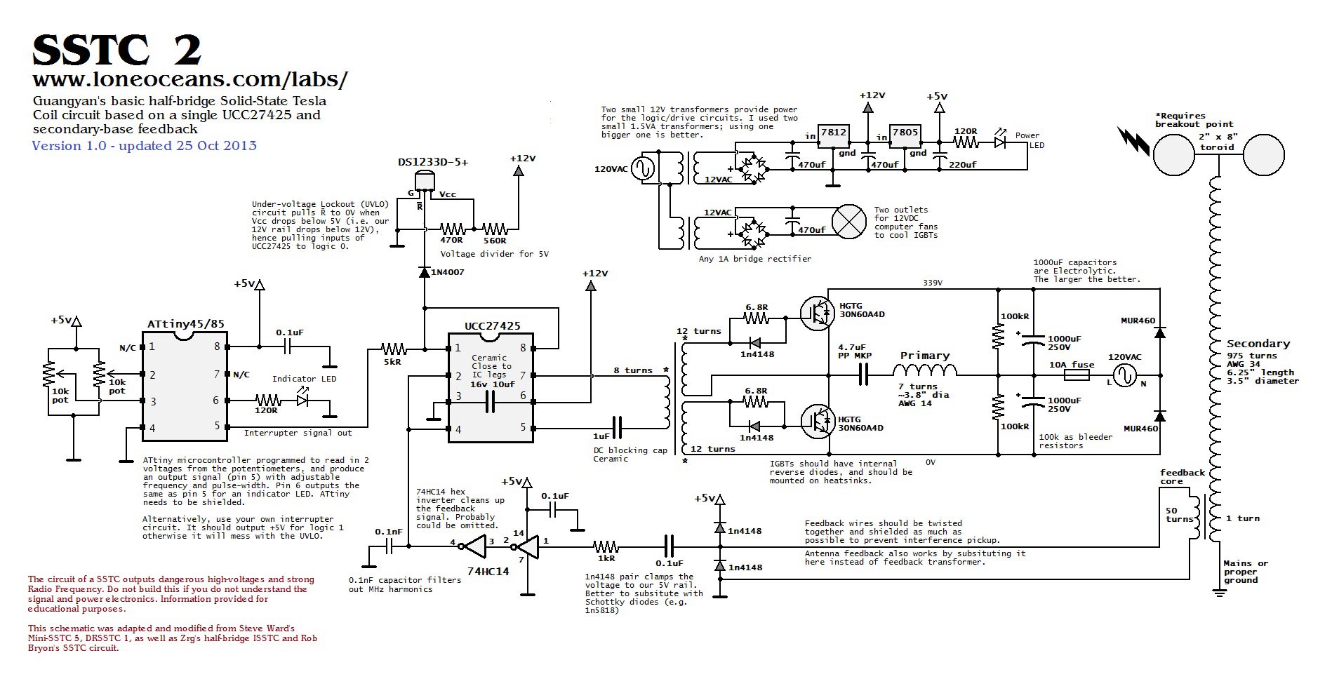
My primary motivation for getting back to this particular project is to enable me to further test my new SSTC2 and verifying everything concerning it before First Light.

Back to Project Signal Generator