Great talk on the value of Making.
Wednesday, May 27, 2015

Wednesday, May 20, 2015
Project Edge Lit Sign - Trying Edge lit Sign Again, PART 1
Revisiting my Edge Lit Sign project. I'm dividing this up into 3 segments due to the separate challenges that I encountered working through each part of this project. This segment addresses just the engraving of the sign, other segments will address the electronics and mounting/housing.
Many, many people have made acrylic
signs illuminated with LED's on the edge. Adding illumination to the edge of the acrylic causes it to
light up only in the areas that it has been cut or engraved. I've
previously tried this using window glass engraved using diamond glass
cutting bits – it didn't end up being very bright (turns out acrylic transmits light better than glass).
With my 3D Printer build last summer, I shelved this project until I had the time to come come back to it and that's what I'm finally doing. Instead of etching glass, this time I'm trying it with acrylic that is custom made for edge lit signs (it is clear but has metal flakes embedded in the acrylic that reflect light when the acrylic is cut), you can find it over at Inventables.
I was inspired to do this sign project as a gift for my wife, she owns and runs a nut free bake shop (Callie's Cuties) and I wanted to make her a fun sign for inside her shop with her logo on it. After getting a vector file of her logo, I opened it up in Inkscape (an open source vector editor). I only changed a few parts of it to make it a little more friendly for engraving on my CNC (primarily different fonts). When I finished my changes I selected the whole graphic and made certain to change it all to a Path (selected Object to Path in the Path drop down menu), then I flipped it to make it a mirror image and then rotated it on its side (to fit the dimensions of my CNC).
After working out the size and layout of the sign I made a cardboard mockup to better visualize what my goal was.
After reviewing this with my wife, I needed to make a few changes - adding "Open" and "Bake Shop". So, the orientation changed and the sign became 8" wide by 10" high instead of 9" wide and 8" wide.
With my 3D Printer build last summer, I shelved this project until I had the time to come come back to it and that's what I'm finally doing. Instead of etching glass, this time I'm trying it with acrylic that is custom made for edge lit signs (it is clear but has metal flakes embedded in the acrylic that reflect light when the acrylic is cut), you can find it over at Inventables.
I was inspired to do this sign project as a gift for my wife, she owns and runs a nut free bake shop (Callie's Cuties) and I wanted to make her a fun sign for inside her shop with her logo on it. After getting a vector file of her logo, I opened it up in Inkscape (an open source vector editor). I only changed a few parts of it to make it a little more friendly for engraving on my CNC (primarily different fonts). When I finished my changes I selected the whole graphic and made certain to change it all to a Path (selected Object to Path in the Path drop down menu), then I flipped it to make it a mirror image and then rotated it on its side (to fit the dimensions of my CNC).
After working out the size and layout of the sign I made a cardboard mockup to better visualize what my goal was.
 |
| measuring and cutting out the cardboard |
 |
| Reversed image to be engraved (should have used normal image) |
 |
| Checking image against acrylic stock |
 |
| Assembling the base |
 |
| Finished base |
 |
| Mockup Done! |
On to my first hurdle, figuring out the feed rate and depth of cut took a bit of trial and error, I'm using a 1/16" single flute end mill by Kyocera (purchased from CarbidePlus). Initially I thought I would need to cut fairly deep into the acrylic cut so my first try was cutting to 0.1" depth (almost 1/2 the thickness of the sheet) with a step down of 0.05" (so 2 passes to reach target depth). First test at 30 in/min was much to fast, I lowered to 20 in/min - still to fast, and then to 10 in/min. Now that I had a good speed I needed to adjust the cut depth for each pass, 0.1" was definitely to deep, it resulted in to much friction and the end mill getting clogged with melted acrylic. In addition to that, I felt I was aiming much to deep for my target depth. I decided on another trial at 8in/min, 0.01" target depth with step down of 0.005". The first pass achieved the results I as looking for.
I changed the cutting parameters in MakerCAM, selecting the entire graphic and using the "follow path" on the CAM menu: tool size 0.0625", depth of cut 0.004", safe height 0.25", step down 0.004". After saving the new G-Code file I placed a new piece of acrylic on the bed and ran the code through Universal G-Code Sender. You can see my result below.
I should note that in my impatience I wasted a sheet of custom acrylic but trying to cut first before determining optimum speeds and depth for my CNC.
I changed the cutting parameters in MakerCAM, selecting the entire graphic and using the "follow path" on the CAM menu: tool size 0.0625", depth of cut 0.004", safe height 0.25", step down 0.004". After saving the new G-Code file I placed a new piece of acrylic on the bed and ran the code through Universal G-Code Sender. You can see my result below.
 |
| Milling the Reversed Image |
 |
| The finished image (before cutting extra stock off) |
I should note that in my impatience I wasted a sheet of custom acrylic but trying to cut first before determining optimum speeds and depth for my CNC.
Saturday, May 16, 2015
Project Theramin - Success... Finally!!!
I've researched Theremin's quite a but over the past few years, in an effort to build my own. Theremin's have a distinctive sound and I've always liked it even when I didn't know what instrument made the sound.
I recently completed a Theremin build, I tried building this particular Theremin 3 times in the past (once on bread board and 2 times on perf board using the wire wrap method), I hayd temporary success on bread board and no success with wire wrap. I set everything aside for about a year and focused on other projects. As I got better at building and troubleshooting I came back to finally conquer this build.
This Theremin is based directly on Art Harrisons Minimum Theremin.
 I made a few, very minor, changes to the circuit:
It did take me awhile before deciding on the cord attachment to the antenna, after aremad bit of trial and error (and some research) I decided to use boot laces as a jacket for the connecting wire (looks similar to antique braided cloth wire jacketing).
The box I used to house this Theremin was a simple box from Micheal's craft store. I removed all the hardware, remade the front panel, added new "antiqued" brass plated hardware. Also, sanded, primed, painted and polyurethaned all the outside surfaces.
I recently completed a Theremin build, I tried building this particular Theremin 3 times in the past (once on bread board and 2 times on perf board using the wire wrap method), I hayd temporary success on bread board and no success with wire wrap. I set everything aside for about a year and focused on other projects. As I got better at building and troubleshooting I came back to finally conquer this build.
This Theremin is based directly on Art Harrisons Minimum Theremin.

- Substituted an LM7805 voltage regulator for the one used in the circuit (the pin out is a bit different)
- Added a power indicator LED
 |
| Finished Theremin |
 |
| Theremin Antenna |
 |
| Housing for Theremin |
 |
| Theremin Circuit board |
 |
| Antenna Connection |
 |
| Rear of Box |
 |
| Hooked up to Guitar Amp |
Thursday, May 14, 2015
Great trip to the MWRRFestival
March 20-22 (2015) was the 3rd annual Midwest RepRap Festival held at the Elkhart County 4H Fairgrounds in Elkhart, IN. There were a lot of cool printers and people at the event, I was only able to attend for a few hours on Saturday (my drive one way was a few hours). Below are a few general overview pics of the people and tables:


I was able to meet the makers of the E3D printer hot-end and got to see the E3D Volcano in action, as well as learning a bit about the technical aspects of it. Actually, when I talked to the 2 of them I didn't know they were the actual developers.
I've been using the E3D v6 for a few months now, originally I got it because of it's versatility (can handle higher temps), the positive user ratings, but what really pushed me to get it was to print Taulman's T-Glase (PET filament), Taulman recommends a larger orifice size when printing with T-Glase to take advantage of optical properties.
Just today, 5/14/15, I finally received my very own Volcano hot end kit, distributors in the US completely sold after the festival, I couldn't find one until last week. Can't wait to install it and try it out (my goal is to dial it in with Taulman Bridge filament).
Hackaday Prize
I've liked the Hackaday site and the Hackaday Prize for quite a while. They are wonderful sources of new ideas and inspiration.
The 2015 competition opened two months ago (when I originally wrote this post) and the focus is on ideas that address important issues effecting lots of people.
I've been brainstorming ideas for a project for the competition and areas I've focused on are:
Water
The 2015 competition opened two months ago (when I originally wrote this post) and the focus is on ideas that address important issues effecting lots of people.
I've been brainstorming ideas for a project for the competition and areas I've focused on are:
Water
- Solar purification/desalination
- Collection techniques - reclaim from air, rain, etc
- Potability measurement device (determine if water is safe to drink)
- more efficient bG testing/measurement
- bG testing method without strips
- bG testing method without using lancet (no finger pricks)
- open source/hardware meter that can utilize multiple strip types
- methods for detecting allergens
- protein based allergens
- other types
- what data can we collect?
Monday, March 16, 2015
Project 3D-Printer and Project CNC - An Update - FINALLY
My DIY 3D-Printer is fully functional (in case you haven't seen my twitter posts). If you want to check out recent prints or files you look at my stuff on My Thingiverse Page.
Changes and additions I've made to my 3D-Printer since September 2014:
Work on CNC left to be done:
 | |||
| State of printer 3/16/15 |
- PCB heated bed
- moved from single PSU to 2 PSU's needed a separate one to supply the bed heater
- Relay board added to switch bed heater on. Pulled signal from gate pin of MOSFET on RAMPS board and wired to a switching transistor and relay
- Increased to full size bed (250 x 250 x 300mm)
- Switched to DRV8825 stepper driver boards (produce less heat as well as handle higher current)
- Hot End - began with a J-head lite, switched to J-Head, now using the E3DV6.
- Numerous iterations and re-designs of my direct drive extruder
- changing all axis to 1/4" - 16 Acme thread rods (feel like it is more dependable since belts need to be checked a lot to ensure good tension)
 | ||
| CNC rebuild 3/16/15 |
- calibrate x, y, and z axii
- mount skate bearing to hold lead-screws on x and y axii
- add lateral stabilizing to spindle mount
- enclose and mount control board and PSU
Monday, September 29, 2014
Project DIY 3D Printer Finally Working
I've been working since the Mokena Maker Faire to get this printer functioning and I've finally done it and here is a picture of it:
 I thought it would be working by the time of the Faire and when it
wasn't I thought it would just be a few days. Instead it's been a few
weeks and I've had to tackle one issue/problem after another.
Here are some close ups of the extruder and hot end:


 Yes, that actually is tape holding the fan on for the hot end.
Below you can see that I desperately need some wire management - I've left that until I got it working since I've needed to constantly change and adjust parts.

 Now for my very first, semi-successful print (a 10x10x10mm cube):
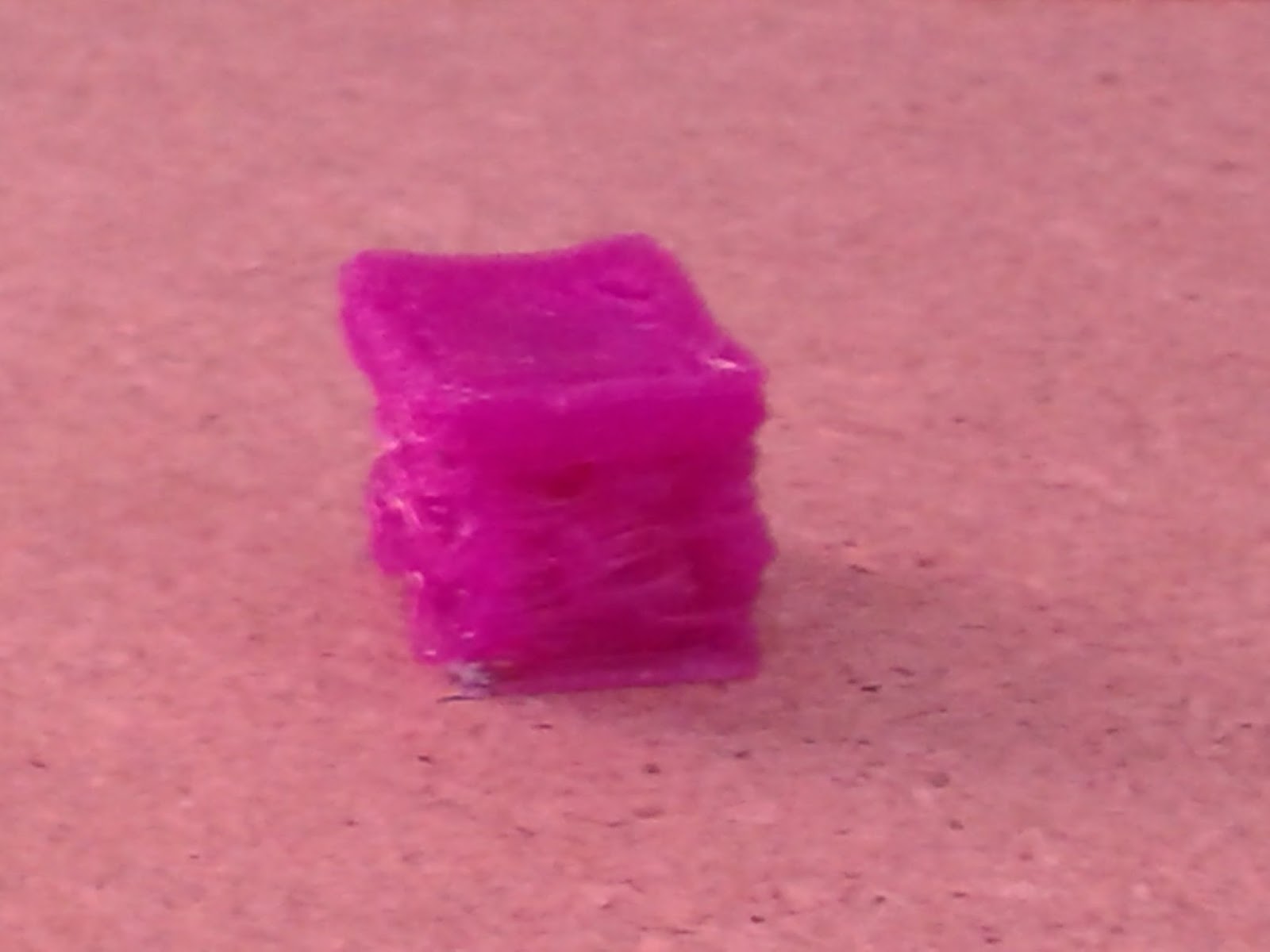 And a progression of adjustments:

 The last pic was a test print of a toy for my daughter.
Here are some close ups of the extruder and hot end:
Below you can see that I desperately need some wire management - I've left that until I got it working since I've needed to constantly change and adjust parts.
Subscribe to:
Posts (Atom)