Monday, December 30, 2013

Project Birdbath Heater - Update

I've survived the Holiday's so far so it's time for a progress update.

I've encountered a few additional problems, ones I anticipated might happen, but hoped would not:
  • Frozen bearing mount - I noticed that my windmill blades did not seem to turn very often, at first I didn't think much about it (wind was pretty minimal) but I finally got curious ad checked.  I found that the bearing that allowed the windmill to rotate into the wind was frozen.
  • Vane on back of windmill - vibration due to wind seems to have worked nuts loose, found vane on the ground under the windmill.
  • Fixing and securing bearing mount (adding set screws) caused the wood to split.
Solution to cracked mount - due to trying to secure bearing with set screws - Zip Ties (they've held up for a week now)

Rudder fell off - screws came loose due to vibration - Zip Ties to the rescue again (still holding up)

New heating element tested (v2a) - using 40 AWG Nichrome wire (18.2cm long)

Cut from steel enclosure from dead Nintendo play station power supply

Before folding closed and sealing with epoxy

The v2a element still did not work successfully. Never really got warm enough to melt the ice.

Newer element, v2b, using 40 AWG nichrome wire wrapped around heat resistant wire insulation harvested from hair curler (or hair dyer - I'm not really sure).  18.2cm of wire wrapped around insulated tubing, then coated with RTV (room temperature vulcanizing) silicone, allowed to dry, inserted into aluminum tubing and sealed with more silicone. This element uses the same length and gauge of wire as v2a but is much more compact (concentrating the heat).  Currently waiting for the silicone to dry and will hopefully test in the morning.


Saturday, December 14, 2013

Project Bird Bath Heater - Windmill Mount Re-Design

Due to the results of my initial test I needed to redesign and build a better mount for my little windmill, one  that allows rotation but is strong enough to stay attached to the pole it is secured to.

I'm hoping that a better idea is to use an actual bearing assembly instead of a caster wheel from an old rolling shelf (at least I think that's what I salvaged it from). My local Ace Hardware carries flanged axial bearings that should be ideal for this. My only issues are: 1.) how to mount the bearing and 2.) how to secure the axle that I need to place inside the bearing (ideally the axle should be hollow so I can run the wiring through it and down the inside of the pole). Well, I guess I also 3.) need to secure the the whole assembly to the pole – so 3 issues to take care of.
Flanged Axial Bearing

Looking up pictures of mounts for flanged axial bearings I mainly came up with cast iron fittings. Not real helpful but then I saw a picture of a bearing used with a spring type shock absorber and it gave me an idea -  If I could drill or bore out a hole in acrylic, or some other material, just big enough to fit the body of the bearing with the lip (or flange) on the edge of the hole – then I could secure it with set screws or glue. I decided to prototype using wood and if it works out I could try acrylic or some type of hardwood.

I had some scrap 1”x3” poplar board so I decided to use that. Below is what I came up with. Initially I was going to use just 2 layers – 1 for the bearing and 1 for the conduit. But, thought about it and decided to use 2 layers for the conduit connection (providing about 1 ½” overlap of the conduit pipe. Initially, I am just screwing these layers together with galvanized deck screws after sealing the pieces with paint. If this works I'll try and get something better like teak to make the mount out of and round out the corners to make it look nicer. But my first objective is to actually get this functioning.
 
Wood Layers Drilled out for Bearing and Pole

Stacked Mount

Rt. to Lft.  Locking ring, Bronze Flanged Sleeve Bearing, Flanged Axial Bearing

Bearing assembly

Bearing assembly with windmill body attached

Bearing Mount, Support Pole, Lynch Pin (to secure to mount to pole)

Lynch Pin Inserted

Windmill Mount all together (before painting and wiring)

Yesterday I painted the wood in the hope that it will help protect it from the elements (and allow the mount to last longer so this idea can be fully tested). Today the paint is fully dry so I can begin assembling the whole thing:
  1. First step is to run the wiring down the pole and out to the rectifier board
  2. Glue (epoxy) the axial bearing into the the wooden mount
  3. Place some type of cap over the top of the bearing assembly to prevent water, snow and ice from entering the pole

Below is a picture of how the wiring enters the support pole:

 I finally found a small plastic box for the rectifier board.  I added a plug so that I'd be able to change heating elements easily (just in case I come up with a more efficient configuration)
Hopefully I'll be able to run another live test tomorrow.

Thursday, December 12, 2013

Project Bird Bath Heater - Update

Here are a few pics of the finished rectifier board:
Top

Bottom
I do plan on enclosing it in some type of box to protect it from the elements but first I want everything up and running.

For my rotating mount I decided to use the same thing I used on my prior mini windmill - a small caster wheel.

My first step was to pry of the plastic wheels:
Below is how I need to position it on the body of the windmill:
To attach it to the body I had to fashion 2 aluminum brackets (from a thinner piece of sheet aluminum - scrap I had left over from a previous project).  On the left in the picture below is one of the pieces that I used to shape and cut the brackets.
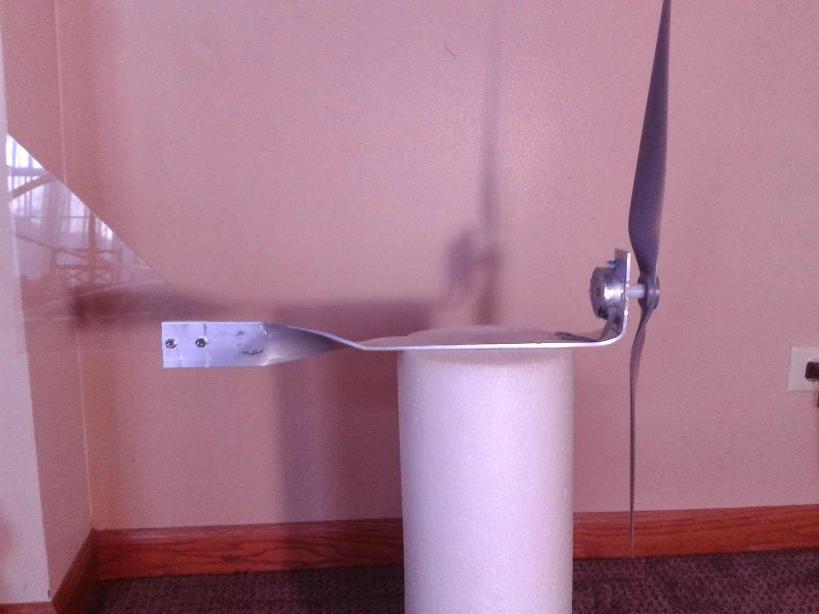
The final assembly, shown below, not attached to the windmill body.  The caster is inserted into a #4 rubber stopper which I used to attach it to the 3/4" conduit pipe (if you look closely you can see the line on the stopper where it met the top of the pipe) that I am using as the pole for the windmill.  With this arrangement I had to run the wires on the outside of the pole, which I was hoping to avoid.


Now on to the Heating Element

Since I couldn't find an adequate element I had to try and fashion one of my own from the nichrome wire harvested from an old hair curler.  I decided on using a 10cm segment wrapped around the mica like in the hair curler.  I then soldered leads taken from the hair curler (since they are insulated with heat resistant insulation) - to solder to the nichrome wire I needed to use an acid base flux.  Below is the wire wrapped around the mica with leads attached, the other mica above and below, and part of the aluminum case on the left:
For the aluminum case I again used a thin piece of sheet aluminum cut down to size - I designed it to be folded over the nichrome and mica bundle, with the sides wrapped around and the top flap folded over separating the 2 leads.  I rough cut the aluminum piece with a hacksaw and refined the shape with small metal files.
prior to folding edges over

ready for the epoxy
I sealed this shut using Loctite Epoxy Weld and soldered leads from the rectifier board to the element long enough to reach the bird bath.

Initial testing took place on Monday afternoon. After pounding a 3 foot galvanized steel pipe 1 foot into the frozen ground – I placed the windmills pole (10 feet long 3/4" galvanized conduit) into the steel pipe. With the wind blowing I tested the voltage across the heating element – I only saw values in the 10's of millivolts. Thinking something must be shorted I took it down and tested all the connections and all the diodes in the rectifier array. Everything was fine, it was only then that I realized that with such a low resistance almost all the voltage was passing through the element so the potential difference from one side to the other would have to be really low - so nothing was wrong and it was working correctly.  I set the windmill back up and placed the heating element in the bird bath and went back inside planning to check on it in an hour to see if any ice was melted.  When I came back to check on it the pole was up but the windmill was on the ground with its prop broken off the motor.  The high winds literally popped the stopper right out of the top of the pole.

I expected to post a wonderful success story but instead I need to back up, look at my assumptions and climb some additional hurdles to learn a bit more about a few things.

I am finishing up a new improved mount for the windmill and re-gluing the propeller to the stepper and hope to have it back up for testing tomorrow.

Saturday, December 7, 2013

Windmill pictures, as promised

This is what the current windmill generator looks like, without:
  1. Final wiring
  2. Rotating mount (so it can turn to face into the wind)
  3. Pole - to situate it above the ground

The propeller and wind vane were both recycled from my initial mini wind generator that I built over the summer.  The body is made from aluminum, that I originally purchased to fabricate propeller blades - I think it cost around $8 and I only used half the of it. 

The propeller is screwed onto a nylon spacer which is in turn secured to the stepper motor shaft (which has a collar with spokes) using Loctite Plastic Bonder Epoxy (I first tried using 2 set screws to lock the nylon spacer to the spoke wheel and then tried hot glue - that secured it long enough for the tests I ran to determine generator output at 15 mph wind speed. It came off after that).  The back of the stepper motor and the board on the side of it that connects to its power cable I coated in clear latex to protect them from water - preventing it from shorting out the or water getting in and freezing inside the motor and locking up the generator.

Some notes concerning height and placement of a windmill.   Ideally it should be at least 30 feet off of the ground since that height removes it from the level of gusts and places it in the area of more consistent air flow.  In addition,  it is generally best to place it as far as possible from other structures - 1) In case the windmill falls over, don't want it to damage any buildings, 2)Nearby structures will interfere with airflow - this even applies to rooftop windmills.  This does not mean you can't place them in these areas, only that they will be less efficient.

This mini-windmill will be fairly close to structures and not very high (planning to place it about 10 feet off the ground).  I need it fairly close to the birdbath to minimize resistive losses from the wires carrying the power.  So, this won't be as efficient a generator as it could be but I shouldn't really need much power.

Friday, December 6, 2013

Bird Bath 3 - more data and start of Windmill Build

After some basic measurements on the Nic-chrome wire, that I harvested from a hair curler, I found:
  • Wire is 36 AWG (5 mil measured by micrometer)
  • Length - 76cm
  • Resistance 74.2 Ohm for entire length
I did some further measurements to determine resistance related to length of wire as well as current draw per length of wire (with stepper motor spinning at 1630 RPM):


1630 RPM
cmOhmmA
1010244.0
2020180.0
3030145.5
4040124.0
5050108.5
606096.0
706986.0 
Pictures in the morning (some fun camera issues).


Thursday, December 5, 2013

Bird Bath Defroster Update

Continuing the Bird Bath Defroster build after a busy holiday break for Thanksgiving.

My first goal was testing the output of the stepper motor at various speeds with output rectified through 2 bridge rectifiers, since this is how I envisioned setting it up outside.
After thinking about how to go about doing this I remembered that my drill press has speeds listed for different pulley configurations.

Placing the axle of the stepper motor in the chuck of the drill press and securing the motor I was able to run it at different speeds and see what voltage and current it can produce.  I tested it with the output open as well as testing it across the heating element from the coffee maker as a load. Testing the heating element with my Multimeter I found that it's resistance was 16.6 ohms. 

RPM VLoad I (mA) VOpen
760 1.9 112 4.75
1150 2.89 166 7.22
1630 3.83 219.9 10.16
2180 4.91 283.4 14.3
3070 6.18 362.7 21.43

Running the stepper at high speed, and connecting the heating element, I checked to see if it would warm up after a few minutes – no matter the speed I did not feel any warmth from the element. I checked the casing of the coffee maker for specifications and realized that it is rated for 900watts – the stepper couldn't generate even 10% of that at the highest speed I tested. 

I also tested the stepper with blades attached to find out what it could output at 15 mph wind speed. I mounted the motor on a wooden plank and held it out my car window while driving at 15 mph (to simulate 15 mph wind speed). The motor was wired through the rectifiers and attached to my Multimeter.  At 15 mph the motor produced 8-10 volts (no load attached) so from previous measurements I assume that it spins at 1150 – 1630 rpm in a 15 mph wind.

Why 15 mph? Checking out wind speed data for Plainfield, Illinois I found that the average annual wind speed is 16.5 mph, with highest speeds in fall and winter and lowest over the summer months. Also, the speedometer on my car is analog not digital so it's easier to estimate 15 (than 16.5).

From this data it definitely appears that I need a different heating element. Searching around my workbench I was able to find the hair curler that I disassembled previously and after some work with a hacksaw, and a screwdriver serving as a pry bar, I removed the heating element:

The element appears to be Ni-chrome wire wrapped around mica and sandwiched between mica (at least I believe it is mica – it looks like it and I know that it is used as a dielectric in some types of capacitors so it is a good electrical insulator).  My next step with the Ni-Chrome wire will be:
  1. measure its thickness/wire gauge
  2. determine resistance per unit length (ohms per cm or per 10 cm)
  3. minimum current at 9 volts to heat wire
If the current needed to heat the wire is low enough to be met by the stepper then I will proceed to making a heating element by encasing the wire in the mica (to electrically insulate it) and then placing that inside aluminum (to transfer the heat to the water).  I do plan on sealing the aluminum closed with epoxy to water proof the wiring (brazing or welding would likely destroy the Ni-Chrome wire).

I will post tomorrow with updates on results.