Tuesday, November 1, 2016

Chicago Southland Mini Maker Faire 2016


A basic word of warning to others: Static Electricity Generators are not a great idea in high humidity conditions (relative humidity inside was over 50%).  My Van De Graaff generator experienced a mess of problems - from belt problems (thankfully I brought a backup with me), alignment of brushes and (of course) output.  The size of my Van De Graaff should make discharges at least a foot long - due to humidity I could only achieve about 1/2 inch.

This years Faire was great, even with the hot and humid weather (we were all, thankfully, inside).
See Pictures below:


Hackday Prize 2016 Round 4 (Home Automation) Winners


Direct Link: Hackaday Prize Home Automation Challange Winners

Thursday, July 21, 2016

Chicago Southland Maker Faire - 3rd Annual

It's just around the corner - The Chicago Southland Maker Faire

August 27th 10am-5pm

About Chicago Southland Mini Maker Faire:

2016 marks the third year of the Chicago Southland Mini Maker Faire (formerly Mokena Mini Maker Faire), held at the Pipefitters Local 597 Training Facility. Organized by SpaceLab and the Mokena Mayor’s Technology Committee, the Chicago Southland Mini Maker Faire has established Mokena as a learning community and technology haven in the south suburbs of Chicago.

Hackaday Prize 2016 - I'm a Round 3 Winner

I'm so amazed, overjoyed and honored that my Universal Glucometer project actually made the Top 20 of the 2016 Hackaday Prize - Citizen Scientist Round .

I've got a lot of work ahead of me - primarily on the coding side, but I'm determined and I WILL get it done, along with a fully functional prototype.

Here is a list of all 20 Winners of Round 3 Citizen Scientist  Round:

Tuesday, July 12, 2016

2016 Hackaday Prize, moving into round 4

So far 3 of the 5 rounds for the Hackaday Prize 2016 (this years theme is - "Build Something That Matters") have finished:
  1. Design Your Concept (March 14 - April 25)
  2. Anything Goes (April 25 - May 30)
  3. Citizen Scientist (May 30 - July 11) just finished, no results yet
 The top entries for rounds 1 and 2 are listed below:

The top 20 projects of theHackaday Prize 2016 "Design Your Concept" challengeare:

The top 20 projects of the 2016 Hackaday Prize "Anything Goes"challenge are:

The Citizen Scientist Challenge (Round 3) just finished yesterday and that marks the start of the Home Automation Challenge (Round 4), to be followed by the Assistive Technologies Challenge (Round 5) which is the last round before finals.

In the next few days we should have news of the to 20 projects in Round 3, that will be added to the list of the top 100 projects going into the Finals.

My 2 entries to the Hackay Prize 2016 (Universal Glucometer and Train Your Brain) have not yet made it to the top 20 of any round so far ( ;( ), but I continue to work on them both.

Project: Universal Glucometer - in the news (well... sort of)

While trying to show a friend my Universal Glucometer entry for the 2016 Hackaday Prize, I came across this article: Hackaday Prize Entry: A Universal Glucose Meter.
It was definitely a nice surprise,  I must have missed notifications in my feeds.

Sunday, June 19, 2016

Project Universal Glucomter - 1st Contact

I posted the basic details of this on Hackaday earlier, thought I's post the some of the nitty gritty details here.

I decided to take a step back and return to some real basic level stuff for programming and using PIC Microcontroller's. First order of business was to ensure my programmer (PICkit3 clone) actually works and that I can actually upload programs (I know compiling programs works but I haven't actually uploaded anything) .  Back when I ordered my last LCD screen (which is actually the wrong one for the reference design from Microchip) I also ordered a few PIC16F877A chips since I have some books that use them for learning to code in C for PIC's.

The first program I wanted to try was the most basic, a simple "Hello World" program that blinks an LED.  The tutorial I worked from was Blink LED with PIC16F877A.  The first hurdle I needed to make it over was how to actually connect the PICkit3 to the micro-controller (in hindsight, if I had started with a Development Board this would not have been an issue). Bread boarding the circuit was no problem from the schematic:


Blinking LED using PIC Microcontroller - Circuit Diagram

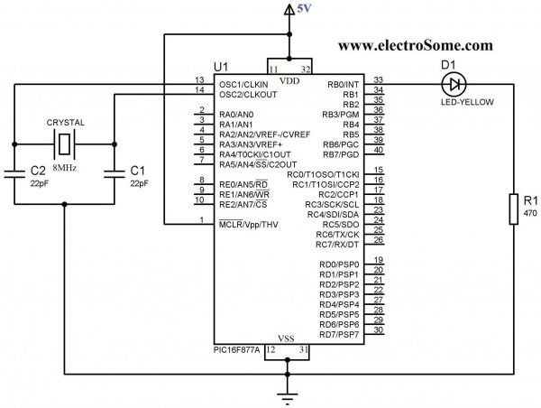
As I put together the circuit on a solderless bread board I realized that I did not order any crystals for the timer oscillator (I'd spent so much time going over the datasheet for the PIC16F1786, from the glucometer reference design, that I never realized that the 877A has no internal oscillator).  After going through crystals I scavenged from old electronics, I found a 4MHz ceramic (3 pin, no need for external capacitors) oscillator.  I didn't really know if it still worked after de-soldering it from devices and I'm not really sure how I could test it but took my chances and used it anyway.

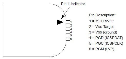
After everything was assembled I needed to connect the PICkit3 programmer.  Pin #1 is designated on the connected by a solid white arrow.  Pin functions are:
1 = MCLR/VPP
2 = VDD Target (power)
3 = VSS (ground)
4 = PGD (ICSPDAT)
5 = PGC (ICSPCLK)
6 = PGM (LVP)

VDD and VSS could easily have confused me but I knew from prior reading that VDD is + power and VSS is ground.  That leaves the other 4 pins - actually 3 since pin 6 is not used here.  Referring to the pin out for the PIC16F877A chip:
The MCLR/Vpp pin is obviously pin 1 of the chip.  Looking at the diagram, you may think , as I did, that pins 25 and 26 are the Clock and Data pins.  As I found out - that is wrong, PGD (ICSPDAT) is the Data pin (pin 40) and PGC (ICSPCLK) is the Clock pin (pin 39).  In addition to this, there are a few other points to consider:
  • 100uF ceramic caps across pins 11/12 and 31/32
  • pullup resistor on MCLR/Vpp (pin 1) - around 5-10K
Before building the project you need to be certain that the Configuration Bits are set correctly and added into the start of the code.  I ended up having to change the oscillator setting to:
#pragma config FOSC = XT        // Oscillator Selection bits (XT oscillator)

My other Configuration Bit settings were:
#pragma config WDTE = OFF       // Watchdog Timer Enable bit (WDT disabled)
#pragma config PWRTE = OFF      // Power-up Timer Enable bit (PWRT disabled)
#pragma config BOREN = ON       // Brown-out Reset Enable bit (BOR enabled)
#pragma config LVP = OFF        // Low-Voltage (Single-Supply) In-Circuit Serial Programming Enable bit (RB3 is digital I/O, HV on MCLR must be used for programming)
#pragma config CPD = OFF        // Data EEPROM Memory Code Protection bit (Data EEPROM code protection off)
#pragma config WRT = OFF        // Flash Program Memory Write Enable bits (Write protection off; all program memory may be written to by EECON control)
#pragma config CP = OFF         // Flash Program Memory Code Protection bit (Code protection off)

It's taken me a few days of reading, trial, and error but I've finally gotten an LED to blink (pretty impressive right!).

Next step is attaching and sending text to a standard 16x2 LCD.

If I have to I will stick with the PIC16F877A, but if I do I'll at least need an external Op-Amp connected (to amplify the signal from the strip).  Hopefully I'll be able to return to the 16F1786 and won't need to deal with that.


Monday, June 13, 2016

Project Updates

Sorry I haven't updated this blog for quite a while - it's due to working on projects over at Hackaday.


I currently have 2 entries for this years Hackaday Prize.
  1. Open Source Neurofeedback (click for details)
  2. Universal Glucometer (click for details)
Challenges I've met along the way:

For my Open Source Neurofeedback project my main challenge continues to be learning to program in Java. 
  • While I do have experience in BASIC, PASCAL, batch files for MS DOS, some C and just a little Python and am reasonably comfortable with linux command line stuff.  While I can read Java programs and understand them, learning to write my own is taking a bit longer than expected.  But, I am starting to get the hang of it.
  • The hardware side of this project is fairly straight forward, even with a few modifications I've made as I've been prototyping.


My Universal Glucometer project has presented me with a number of challenges:
  • While Microchip provides some base code for a glucometer along with a test layout - some parts are no longer available or difficult to find - which goes counter to my idea of a glucometer that can be built from basic parts and adapted to different test strips. Due to these issues I've decided that I need to change code to use a different LCD (the LCD in the Application Note is hard to find - I actually ordered the wrong one -twice - same manufacturer but different pin-out and control protocol).  So, if it is a problem for me to find it now, it'll be worse for others later - need to use an easier to find/source display (maybe a standard 16x2 LCD or a Nokia LCD display - both are easy to get cheap on Ebay).
  • The biggest challenge I've had is figuring my way around Microchip's Microcontrollers: writing code for them and uploading code.  I only recently moved into programming AVR's instead of Arduino's and in hindsight it would have been easier to start with a development board and then worked up to a bare chip (like going from Arduino to AVR's).  It took me awhile, but I finally got MPLAB (Microchip's IDE - Integrated Development Enviornment) installed, along with XC8 (Microchips C compiler for their 8 bit microcontrollers).  I even got the demo program for Glucose Meter to compile. I am still trying to upload it to the actual microcontroller using MPLAB and PICkit3.

Wednesday, April 20, 2016

Project - Neurofeedback EEG Mindflex to MindWaveMobile Headset Part 2 (Details)

Configuring the TGAM1 board for raw EEG data (57600 baud)

Click here to go to part one


    • The default output baud rate for TGAM1 boards (at least the ones taken out of Mindflex and Force Trainer headsets) is 9600 baud (this only allows you to capture data for the default frequency bands once per second).
    • To use these cheap headsets with apps made to work with "Think Gear" headsets - we need to change the communication rate to 57600 baud.  There are 2 methods to achieve this:
      1. One way involves programming the TGAM1 board over Bluetooth - if you look through the links at the end of this post you'll find ways of doing this.  I did not do it this way, instead I chose the second method.
      2. The second way involves removing a single SMD (surface mount) resistor (pull-down resistor) and adding a different resistor going from the same area and then over to positive connection of the power supply on the TGAM1 board (pull-up resistor).
        • To do this you'll only need:
          1.  Basic soldering iron
          2. 10k 1/8th watt resistor
          3. Heat shrink tubing to insulate the resistor
    • Step 1: Remove SMD Resistor (surface mount resistor, it a little rectangle on the top of the board.
      • The SMD resistor can be removed by heating up the pad with a soldering iron and pulling it off with tweezers (or, if you are brave - snap it off with needle nose pliers).
    • Step 2 - Solder in the 10k through hole -(meaning is has wires) resistor.
      • the 10k resistor goes from the spot marked B1 on the board and goes over to the positive power connection (refer to the labeled picture at the top of this post)

    Setting up the HC-06(?) Bluetooth Host/ Slave Module (SPP – Serial Port Profile).

    Setting up the Bluetooth communication board/module:
    • Configuring the Bluetooth Slave Module for 57600 baud rate (most modules seem to be configured for 9600 baud rate as the default setting) **This step should be done with the Bluetooth Module alone (not connected to the TGAM1 board)**
      • This is where we need some type of USB to TTL serial converter
        • The easiest is to use an Arduino Board and load a 'Sketch' to connect to the Bluetooth Module over the serial console. 
        • Breadboard wiring (from Fritzing - just pretend the HC-05 is an HC-06 Slave)
        • So, you need:
          • An Arduino (I like the Nano since its made for bread boards - but you could use an Uno, etc.)
          • Logic Level Shifter
          • HC-06 Bluetooth Breakout Board
          • Arduino sketch to send commands to the HC-06 (HC-06 Setup ).
    •  Physical connections of Bluetooth Serial board to TGAM1board pics
      • I used 90 degree male pin headers so I could use cables
      • Bluetooth RX pin to TGAM1 TX pin
      • Bluetooth TX pin to TGAM1 RX pin
        • Vcc to 3.3v source (if you are using the Mindwave or Force Trainer headset use the on board regulated voltage)
        • Gnd - make sure the TGAM1 and HC-06 (or -05) grounds are connected together
        • LED on Bluetooth Module
          • When initially connected to power it should blink
            • There are different flashing rates that depend on default baud rates
            • Vast majority of modules are set at 9600 as the default baud rate
          • LED will stay lit constantly after the device is paired
            • actually a little more complicated – stays lit constantly when paired and ACTIVELY sending data to application (while setting up my module, I couldn't understand why it would say it was paired and the light on the board continued to blink. Even after I attached it to the headset and powered it on again – it continued to blink – computer said it was paired. FINALLY, after installing Neurosky's Mindwave Mobile and starting the Brain Wave Visualizer – it stayed lit. After I closed Mindwave Mobile it began blinking again. I mention all this because, I didn't see it stated anywhere else.)

      Some REALLY BASIC! Background on Bluetooth Communication

      Being very, very new to working with Bluetooth, myself, I decided to include some additional information so that others can hopefully avoid making the same mistakes that I've made:

      Slave vs Master
      • Master is the device at the center of a Bluetooth network (in this case – your phone, tablet or computer)
        • a Master can pair with multiple Slave devices
      • Slaves send and receive data only to or from the Master (in this case – the MindFlex headset, you could, conceivably,  pair multiple headsets to one Master device)
        • a Slave can only be paired to 1 Master at a time
      Pairing
      • Bonds Slave device to Master device
      • After pairing devices automatically connect when they are both powered on and close enough
        • uses authentication data saved on the 2 devices
      Profiles (devices need to support the same profile to communicate - "communication profiles") – this is not an exhaustive list
      • HSP -head set profile
      • HFP – hands free profile
      • HID – human interface device (generally a keyboard, mouse, etc.)
      • SPP – serial port profile (this is what we need for communication)
      • A2DP – advanced audio distribution profile (streaming audio data to speakers, etc)
      • AVRCP – A/V remote control profile (Bluetooth remote for TV, etc.)
      - A little note on profiles and their importance: I have an older android smartphone (Bluetooth and WiFi capable), an IPhone 5 and a Kindle Fire.  It turns out that none of them support the Bluetooth Serial Port Profile and as a result the only way I can use the Bluetooth connection is with my laptop and a Bluetooth USB dongle.  So, if you are planning to use this with a specific device make sure to check if it supports SPP (Serial Port Profile) Bluetooth Profile.
      • First modules I purchased were actually just back planes (essentially just the breakout board without the module – read descriptions very carefully – not a costly mistake but annoying)

      • The next module was a Master – (projects I looked at never seemed to mention if I needed a Master or Slave module... well it turns out I needed a Slave module, of course)

      • Finally got an HC-06 Slave Module

      AT Commands

      You can find these on the datasheets for the Bluetooth Serial Modules (you can find them online - none of the ones I ordered included the datasheet).  AT commands apply to both the HC-05 and HC-06 boards. These are the ones we need to setup the HC-06 breakout:
        • AT pings the device (response back “OK”over serial)
        • AT+PINxxx
        • AT+NAMExxx
        • AT+BAUD4 (sets baudrate to 9600 – default rate)
        • AT+BAUD7 (sets baudrate to 57600)

        Links to more information and resources:


        Wednesday, April 13, 2016

        Hackaday World Create Day 2016 and Hackaday Prize 2016


        Only 1 week from this Saturday, on April 23rd, it's:

        I'll be hosting a Meetup in Plainfield, IL at the Plainfield Public Library to meet and brainstorm ideas for entries to this years Hackaday Prize. Plainfield, IL World Create Day

        From Hackaday.io:
        Create tech solutions for social change on Hackaday World Create Day, our worldwide brainstorming session for the 2016 Hackaday Prize design concept challenge! Join teams from around the globe and submit ideas for projects that solve problems in categories from citizen science to assistive technologies, or anything else that leverages your hardware, coding, scientific, design and mechanical skills.
        We’ll be picking the most spectacular design solutions to share on the Hackaday front page, and there will be prizes. But we also want to celebrate the fun of getting together in person with all of the people who make Hackaday a part of their daily ritual, so share your photos and ideas with hashtag #WorldCreateDay!

        The Goal:

        Form a team (or work on your own) and submit a project to the Hackaday Prize design challenge. See challenge details here: https://hackaday.io/prize/details#one
        Need some inspiration for your project? Here are some ideas:
        • Citizen Science - Build a graphene supercapacitor, study the effects of a behavior, build an open source instrumentation device.
        • Automation - Build a device that makes breakfast or buys laundry detergent when you’re running low. Automatically track stuff, automate any process, build a Me-robot to do your every whim
        • Assistive technologies - Build a project that helps others move better, see better, or live better. Whether that means exoskeletons, a better wheelchair, a braille display, or educational software, we want to see it.
        • Or any other idea you have to hack for social change! Leverage your talent and find solutions to address technology issues facing humanity today.

        Beyond Hackaday World Create Day Meetup

        Hackaday World Create Day is a single event, but your meetup can live on if you want it to. We can help with ideas for future meetups of your group. This is a great way to show that the Hackaday community is alive and thriving in your part of the world. Maybe our next big event will be held in your city!


        Monday, January 11, 2016

        Project SSTC2 - Part 2 (Just a quick update - more to come)

        Current issues that I'm addressing (to finish this coil).  I want to do it right so I'm trying not to rush it (even though I want to - just so I can have it done).
        • rewinding secondary coil (DONE)
          • My initial coil I ruined when I tried removing some inclusions trapped in the resin coat I applied - ended up pulling and breaking one winding.
          • Decided to completely rewind new coil (wanted it to look good)
            • made a winding rig and cut winding time in half
        • Question regarding capacitor on MOSFET gate drive chip in Guangyan's schematic
          • The datasheet for the UCC27425 and schematic differ.  Page 10 of the datasheet recommends 
            • "two VDD bypass capacitors are recommended to prevent noise problems. The use of surface mount components is highly recommended. A 0.1-μF ceramic capacitor should be located closest to the VDD to ground connection. In addition, a larger capacitor (such as 1-μF) with relatively low ESR should be connected in parallel, to help deliver the high current peaks to the load."
        • Primary Side of coil
          • voltage double (DONE)
            • difficulty finding capacitors that I could pull from older scrap
            • ended up breaking down and ordering them
          • Concerned about minimizing stray inductance in half bridge (DONE)
            • etching/making multi layer pcb (unable to)
            • make connections with copper sheet/plate
              • unable to solder to wider or thicker copper
                • heat conductivity of copper so high that entire area would need to be heated enough to melt and bond solder which would require higher temps for a longer period of time (would end up killing sensitive components).
            • compromised by using narrower copper sheet/plate
        • Want to get an actual measure of the resonant frequency of my secondary coil
          • Need to finish making a working Frequency/signal generator (DONE)
            • AD9850 working - set up to scan from 100kHz to 200kHz (as a start, each second frequency increases by 1kHz) - Yes I'll be posting an update to my AD9850 Signal Generator Project.
        • Finish making a nicer looking Topload for Secondary Coil
          • Not an immediate concern - I do have Topload's I can use for testing
        •  Make shielded enclosure for electronics
        • Add optical connection for external interrupter
          • Also not an immediate concern - more something to add after all is working reliably.
        SSTC2 part 1

        Project - Biofeedback EEG Mindflex to MindWaveMobile Headset

        Converting a Mindflex to a MindWaveMobile Headset

        This basically involves adding a Bluetooth serial transmitter (and configuring it) to the Mindflex Headset and changing some components on the TGAM1 board (the board that acquires the EEG data).

        This ended up being a bit of an adventure – even after a good deal of research (reading datasheet's very carefully) and reviewing other peoples tutorials of similar hacks. In the end, it took about a week of part time research on components, Bluetooth (profiles, module boards, communication protocols), TGAM1 board (communication protocols, identifying board connection points, hardware settings etc.). Presently, I have a fully functional headset that is recognized by Neurosky's MindWaveMobile software as a MindWave Mobile Headset.

        Hardware:

        • Mindflex Headset ($10-20 on ebay)
        • HC-06 Bluetooth Slave Module (that communicates with Serial Port Profile (SPP))
          • these are between $5-10 on Amazon or Ebay (cheaper in quantity, or if you are willing to wait, from China)
          • should be able to use an HC-05 also (connections and configurations a little different – HC-05 can be configured either as a Master or a Slave module – unlike HC-06 which is only one or the other)
          • I'm a noob concerning Bluetooth: protocols, host modes, etc.
        • 10k resistor (pull up to set TGAM board to 57600 baud, ¼ or 1/8 watt)
        • Hookup wire

        Tools:

        • Soldering iron (and solder, of course)
        • Multi-Tester/VOMeter (non-essential - mainly to verify connections)
        • Magnifier (non-essential - to see TGAM1 board pins and labels clearly)
        • 5V to 3.3V Level Shifter (essential if using an Arduino board to set up the Bluetooth module, non-essential otherwise)
        • Some type of USB to TTL Serial Converter (for setting up Bluetooth module board)
          Some Options for Setting Up HC-06 Module
            • Only need 4 pins (Power, GND, TX, RX)
               
          • Adafruit's Console Cable - USB to TTL Serial Cable - Debug / Console Cable https://www.adafruit.com/product/954.There are four wires:
            • red (power)
            • black (GND)
            • white (RX) into USB port
            • green (TX) out of the USB port.
              • The power pin provides the 5V @ 500mA direct from the USB port and the RX/TX pins are 3.3V level for interfacing with the most common 3.3V logic level chipsets.
            • Initially, this is what I was using (at first it was working through a terminal program using serial communication – then it just stopped working. It turns out I need a newer chipset for it to work correctly on Windows 10)
               
          • BusPirate – this should work with no problem when combined with a terminal program (Teraterm, Putty, etc) in serial mode
             
          • Arduino Board with USB connection
            • Software Serial sketch
              • This is what I ended up using and it worked fine – though you do need to upload the sketch a few times:
                • Change baud rate of module
                • change software serial baud rate – reload
                • etc.

        Here are a couple of screen shots of the headset working with a couple of applications:


         I'll post a full write up of this build soon.

        Wednesday, January 6, 2016

        Project Signal Generator: AD9850 DDS Board

        I've been messing with an AD9850 DDS Board, on and off, for a while now.  Initially I thought I'd just be able to replicate some one else's project, like the following ones from Instructables:
        But, for various reasons I couldn't get things to work how I wanted them to.  I also looked at different Arduino Libraries for the AD9850 and had problems understanding the different functions in the libraries and how to call them, etc. (primarily due to my beginner/noob skills in programming).  As a result,I decided to take a step back and go to a more basic and direct level and not use a Library but instead just write more direct code.

        My first step is to really dig into the datasheet for the AD9850  - (this is the datasheet for the chip from Analog Devices).
        Important Info from datasheet:
        • PSU to chip/board is 5V
        • logic levels are also 5V
        • Important Pins: (descriptions on p5 of the datasheet)
          • Vcc
          • GND
          • D7 - this is our serial data input pin
          • W-CLK - Word Load Clock (our clock pin for loading serial data) - when pulled high it loads next bit into register then pull low before starting over with next bit
          • FQUP - Frequency Update Pin (like a latch pin for a shift register) - pulled high then low to enable serial mode and again after filling register to load bits in to update frequency (not completely clear in datasheet)
          • RESET - Master Reset for board and registers on board (need to perform at start and possibly before each time frequency is updated/changed)
        The Serial Enable and Load sequence is on p12 of the datasheet. Another important detail is the timing diagrams on p11 (list the minimum times between clock pulses, etc as well as the minimal pulse width's).

        To set the frequency of the AD9850 we need to load a 40 bit word through the D7(serial data loading pin). This is summarized on page 9 of the datasheet: 32 bits set the frequency, 3 bits for control and power down, 5 bits for the phase shift of the frequency. Page's 12 and 13 give better information on the sequences for powering on the chip, resetting the registers, loading the registers and powering off the chip.  Bits 32, 33 and 34 should all be set to 0 (binary) to avoid powering down chip or enabling factory test modes.

        I will post a clearer run down on addressing this chip/board serially (bit order, timing sequence, etc.) once I get back to my workbench to actually test everything.

        A quick note: the AD9850 DDS board I am using I ordered on ebay from NYPlatform (that's the link to the store, since they change their listings regularly).  A labeled picture of the board as well as the board schematic are below:

        My primary motivation for getting back to this particular project is to enable me to further test my new SSTC2 and verifying everything concerning it before First Light.

        Back to Project Signal Generator