I decided to take a step back and return to some real basic level stuff for programming and using PIC Microcontroller's. First order of business was to ensure my programmer (PICkit3 clone) actually works and that I can actually upload programs (I know compiling programs works but I haven't actually uploaded anything) . Back when I ordered my last LCD screen (which is actually the wrong one for the reference design from Microchip) I also ordered a few PIC16F877A chips since I have some books that use them for learning to code in C for PIC's.
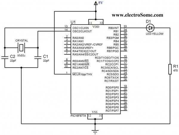
The first program I wanted to try was the most basic, a simple "Hello World" program that blinks an LED. The tutorial I worked from was Blink LED with PIC16F877A. The first hurdle I needed to make it over was how to actually connect the PICkit3 to the micro-controller (in hindsight, if I had started with a Development Board this would not have been an issue). Bread boarding the circuit was no problem from the schematic:

As I put together the circuit on a solderless bread board I realized that I did not order any crystals for the timer oscillator (I'd spent so much time going over the datasheet for the PIC16F1786, from the glucometer reference design, that I never realized that the 877A has no internal oscillator). After going through crystals I scavenged from old electronics, I found a 4MHz ceramic (3 pin, no need for external capacitors) oscillator. I didn't really know if it still worked after de-soldering it from devices and I'm not really sure how I could test it but took my chances and used it anyway.
After everything was assembled I needed to connect the PICkit3 programmer. Pin #1 is designated on the connected by a solid white arrow. Pin functions are:
1 = MCLR/VPP
2 = VDD Target (power)
3 = VSS (ground)
4 = PGD (ICSPDAT)
5 = PGC (ICSPCLK)
6 = PGM (LVP)
VDD and VSS could easily have confused me but I knew from prior reading that VDD is + power and VSS is ground. That leaves the other 4 pins - actually 3 since pin 6 is not used here. Referring to the pin out for the PIC16F877A chip:
The MCLR/Vpp pin is obviously pin 1 of the chip. Looking at the diagram, you may think , as I did, that pins 25 and 26 are the Clock and Data pins. As I found out - that is wrong, PGD (ICSPDAT) is the Data pin (pin 40) and PGC (ICSPCLK) is the Clock pin (pin 39). In addition to this, there are a few other points to consider:
- 100uF ceramic caps across pins 11/12 and 31/32
- pullup resistor on MCLR/Vpp (pin 1) - around 5-10K
#pragma config FOSC = XT // Oscillator Selection bits (XT oscillator)
My other Configuration Bit settings were:
#pragma config WDTE = OFF // Watchdog Timer Enable bit (WDT disabled)
#pragma config PWRTE = OFF // Power-up Timer Enable bit (PWRT disabled)
#pragma config BOREN = ON // Brown-out Reset Enable bit (BOR enabled)
#pragma config LVP = OFF // Low-Voltage (Single-Supply) In-Circuit Serial Programming Enable bit (RB3 is digital I/O, HV on MCLR must be used for programming)
#pragma config CPD = OFF // Data EEPROM Memory Code Protection bit (Data EEPROM code protection off)
#pragma config WRT = OFF // Flash Program Memory Write Enable bits (Write protection off; all program memory may be written to by EECON control)
#pragma config CP = OFF // Flash Program Memory Code Protection bit (Code protection off)
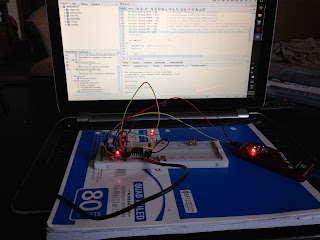
It's taken me a few days of reading, trial, and error but I've finally gotten an LED to blink (pretty impressive right!).
Next step is attaching and sending text to a standard 16x2 LCD.
If I have to I will stick with the PIC16F877A, but if I do I'll at least need an external Op-Amp connected (to amplify the signal from the strip). Hopefully I'll be able to return to the 16F1786 and won't need to deal with that.

