Showing posts with label diabetes. Show all posts

Tuesday, November 1, 2016

Chicago Southland Mini Maker Faire 2016


A basic word of warning to others: Static Electricity Generators are not a great idea in high humidity conditions (relative humidity inside was over 50%).  My Van De Graaff generator experienced a mess of problems - from belt problems (thankfully I brought a backup with me), alignment of brushes and (of course) output.  The size of my Van De Graaff should make discharges at least a foot long - due to humidity I could only achieve about 1/2 inch.

This years Faire was great, even with the hot and humid weather (we were all, thankfully, inside).
See Pictures below:


Tuesday, July 12, 2016

Sunday, June 19, 2016

Project Universal Glucomter - 1st Contact

I posted the basic details of this on Hackaday earlier, thought I's post the some of the nitty gritty details here.

I decided to take a step back and return to some real basic level stuff for programming and using PIC Microcontroller's. First order of business was to ensure my programmer (PICkit3 clone) actually works and that I can actually upload programs (I know compiling programs works but I haven't actually uploaded anything) .  Back when I ordered my last LCD screen (which is actually the wrong one for the reference design from Microchip) I also ordered a few PIC16F877A chips since I have some books that use them for learning to code in C for PIC's.

The first program I wanted to try was the most basic, a simple "Hello World" program that blinks an LED.  The tutorial I worked from was Blink LED with PIC16F877A.  The first hurdle I needed to make it over was how to actually connect the PICkit3 to the micro-controller (in hindsight, if I had started with a Development Board this would not have been an issue). Bread boarding the circuit was no problem from the schematic:
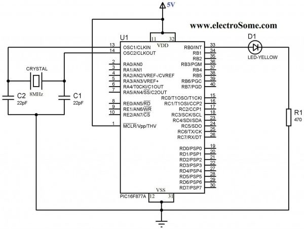


Blinking LED using PIC Microcontroller - Circuit Diagram

As I put together the circuit on a solderless bread board I realized that I did not order any crystals for the timer oscillator (I'd spent so much time going over the datasheet for the PIC16F1786, from the glucometer reference design, that I never realized that the 877A has no internal oscillator).  After going through crystals I scavenged from old electronics, I found a 4MHz ceramic (3 pin, no need for external capacitors) oscillator.  I didn't really know if it still worked after de-soldering it from devices and I'm not really sure how I could test it but took my chances and used it anyway.

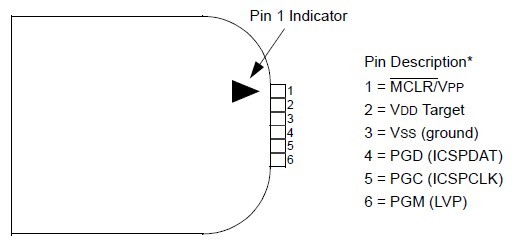
After everything was assembled I needed to connect the PICkit3 programmer.  Pin #1 is designated on the connected by a solid white arrow.  Pin functions are:
1 = MCLR/VPP
2 = VDD Target (power)
3 = VSS (ground)
4 = PGD (ICSPDAT)
5 = PGC (ICSPCLK)
6 = PGM (LVP)

VDD and VSS could easily have confused me but I knew from prior reading that VDD is + power and VSS is ground.  That leaves the other 4 pins - actually 3 since pin 6 is not used here.  Referring to the pin out for the PIC16F877A chip:
The MCLR/Vpp pin is obviously pin 1 of the chip.  Looking at the diagram, you may think , as I did, that pins 25 and 26 are the Clock and Data pins.  As I found out - that is wrong, PGD (ICSPDAT) is the Data pin (pin 40) and PGC (ICSPCLK) is the Clock pin (pin 39).  In addition to this, there are a few other points to consider:
  • 100uF ceramic caps across pins 11/12 and 31/32
  • pullup resistor on MCLR/Vpp (pin 1) - around 5-10K
Before building the project you need to be certain that the Configuration Bits are set correctly and added into the start of the code.  I ended up having to change the oscillator setting to:
#pragma config FOSC = XT        // Oscillator Selection bits (XT oscillator)

My other Configuration Bit settings were:
#pragma config WDTE = OFF       // Watchdog Timer Enable bit (WDT disabled)
#pragma config PWRTE = OFF      // Power-up Timer Enable bit (PWRT disabled)
#pragma config BOREN = ON       // Brown-out Reset Enable bit (BOR enabled)
#pragma config LVP = OFF        // Low-Voltage (Single-Supply) In-Circuit Serial Programming Enable bit (RB3 is digital I/O, HV on MCLR must be used for programming)
#pragma config CPD = OFF        // Data EEPROM Memory Code Protection bit (Data EEPROM code protection off)
#pragma config WRT = OFF        // Flash Program Memory Write Enable bits (Write protection off; all program memory may be written to by EECON control)
#pragma config CP = OFF         // Flash Program Memory Code Protection bit (Code protection off)

It's taken me a few days of reading, trial, and error but I've finally gotten an LED to blink (pretty impressive right!).

Next step is attaching and sending text to a standard 16x2 LCD.

If I have to I will stick with the PIC16F877A, but if I do I'll at least need an external Op-Amp connected (to amplify the signal from the strip).  Hopefully I'll be able to return to the 16F1786 and won't need to deal with that.


Monday, June 13, 2016

Project Updates

Sorry I haven't updated this blog for quite a while - it's due to working on projects over at Hackaday.


I currently have 2 entries for this years Hackaday Prize.
  1. Open Source Neurofeedback (click for details)
  2. Universal Glucometer (click for details)
Challenges I've met along the way:

For my Open Source Neurofeedback project my main challenge continues to be learning to program in Java. 
  • While I do have experience in BASIC, PASCAL, batch files for MS DOS, some C and just a little Python and am reasonably comfortable with linux command line stuff.  While I can read Java programs and understand them, learning to write my own is taking a bit longer than expected.  But, I am starting to get the hang of it.
  • The hardware side of this project is fairly straight forward, even with a few modifications I've made as I've been prototyping.


My Universal Glucometer project has presented me with a number of challenges:
  • While Microchip provides some base code for a glucometer along with a test layout - some parts are no longer available or difficult to find - which goes counter to my idea of a glucometer that can be built from basic parts and adapted to different test strips. Due to these issues I've decided that I need to change code to use a different LCD (the LCD in the Application Note is hard to find - I actually ordered the wrong one -twice - same manufacturer but different pin-out and control protocol).  So, if it is a problem for me to find it now, it'll be worse for others later - need to use an easier to find/source display (maybe a standard 16x2 LCD or a Nokia LCD display - both are easy to get cheap on Ebay).
  • The biggest challenge I've had is figuring my way around Microchip's Microcontrollers: writing code for them and uploading code.  I only recently moved into programming AVR's instead of Arduino's and in hindsight it would have been easier to start with a development board and then worked up to a bare chip (like going from Arduino to AVR's).  It took me awhile, but I finally got MPLAB (Microchip's IDE - Integrated Development Enviornment) installed, along with XC8 (Microchips C compiler for their 8 bit microcontrollers).  I even got the demo program for Glucose Meter to compile. I am still trying to upload it to the actual microcontroller using MPLAB and PICkit3.

Wednesday, April 13, 2016

Hackaday World Create Day 2016 and Hackaday Prize 2016


Only 1 week from this Saturday, on April 23rd, it's:

I'll be hosting a Meetup in Plainfield, IL at the Plainfield Public Library to meet and brainstorm ideas for entries to this years Hackaday Prize. Plainfield, IL World Create Day

From Hackaday.io:
Create tech solutions for social change on Hackaday World Create Day, our worldwide brainstorming session for the 2016 Hackaday Prize design concept challenge! Join teams from around the globe and submit ideas for projects that solve problems in categories from citizen science to assistive technologies, or anything else that leverages your hardware, coding, scientific, design and mechanical skills.
We’ll be picking the most spectacular design solutions to share on the Hackaday front page, and there will be prizes. But we also want to celebrate the fun of getting together in person with all of the people who make Hackaday a part of their daily ritual, so share your photos and ideas with hashtag #WorldCreateDay!

The Goal:

Form a team (or work on your own) and submit a project to the Hackaday Prize design challenge. See challenge details here: https://hackaday.io/prize/details#one
Need some inspiration for your project? Here are some ideas:
  • Citizen Science - Build a graphene supercapacitor, study the effects of a behavior, build an open source instrumentation device.
  • Automation - Build a device that makes breakfast or buys laundry detergent when you’re running low. Automatically track stuff, automate any process, build a Me-robot to do your every whim
  • Assistive technologies - Build a project that helps others move better, see better, or live better. Whether that means exoskeletons, a better wheelchair, a braille display, or educational software, we want to see it.
  • Or any other idea you have to hack for social change! Leverage your talent and find solutions to address technology issues facing humanity today.

Beyond Hackaday World Create Day Meetup

Hackaday World Create Day is a single event, but your meetup can live on if you want it to. We can help with ideas for future meetups of your group. This is a great way to show that the Hackaday community is alive and thriving in your part of the world. Maybe our next big event will be held in your city!