Showing posts with label music. Show all posts

Thursday, March 25, 2021

Multiple Project Updates Coming Soon

I've been working to update a number of projects that have been sitting on my to do shelf for way to long.  In the next few weeks I'll be doing write ups on the following:

  • Rebuild of my 12kV (~900Watt) Spark Gap Tesla Coil (Old Sparky). Mainly a build of a new DIY low inductance High Voltage capacitor that should allow for better resonance and energy transfer (and bigger arc's).

  • My DRSSTC build using OneTesla parts - I couldn't afford the complete OneTeslaTS kit so many of the parts I've fabricated on my own.


  • Further work on my Voight Kampff machine - its been a long break but I'm back at it


Monday, January 11, 2016

Project SSTC2 - Part 2 (Just a quick update - more to come)

Current issues that I'm addressing (to finish this coil).  I want to do it right so I'm trying not to rush it (even though I want to - just so I can have it done).
  • rewinding secondary coil (DONE)
    • My initial coil I ruined when I tried removing some inclusions trapped in the resin coat I applied - ended up pulling and breaking one winding.
    • Decided to completely rewind new coil (wanted it to look good)
      • made a winding rig and cut winding time in half
  • Question regarding capacitor on MOSFET gate drive chip in Guangyan's schematic
    • The datasheet for the UCC27425 and schematic differ.  Page 10 of the datasheet recommends 
      • "two VDD bypass capacitors are recommended to prevent noise problems. The use of surface mount components is highly recommended. A 0.1-μF ceramic capacitor should be located closest to the VDD to ground connection. In addition, a larger capacitor (such as 1-μF) with relatively low ESR should be connected in parallel, to help deliver the high current peaks to the load."
  • Primary Side of coil
    • voltage double (DONE)
      • difficulty finding capacitors that I could pull from older scrap
      • ended up breaking down and ordering them
    • Concerned about minimizing stray inductance in half bridge (DONE)
      • etching/making multi layer pcb (unable to)
      • make connections with copper sheet/plate
        • unable to solder to wider or thicker copper
          • heat conductivity of copper so high that entire area would need to be heated enough to melt and bond solder which would require higher temps for a longer period of time (would end up killing sensitive components).
      • compromised by using narrower copper sheet/plate
  • Want to get an actual measure of the resonant frequency of my secondary coil
    • Need to finish making a working Frequency/signal generator (DONE)
      • AD9850 working - set up to scan from 100kHz to 200kHz (as a start, each second frequency increases by 1kHz) - Yes I'll be posting an update to my AD9850 Signal Generator Project.
  • Finish making a nicer looking Topload for Secondary Coil
    • Not an immediate concern - I do have Topload's I can use for testing
  •  Make shielded enclosure for electronics
  • Add optical connection for external interrupter
    • Also not an immediate concern - more something to add after all is working reliably.
SSTC2 part 1

Tuesday, December 15, 2015

Project SSTC2 - Small tabletop coil

I've been at work on this coil for a while now (taking it slow and careful in an effort to limit my release of magic blue smoke as much as possible).  This coil design I credit to Gao Guangyan and his 
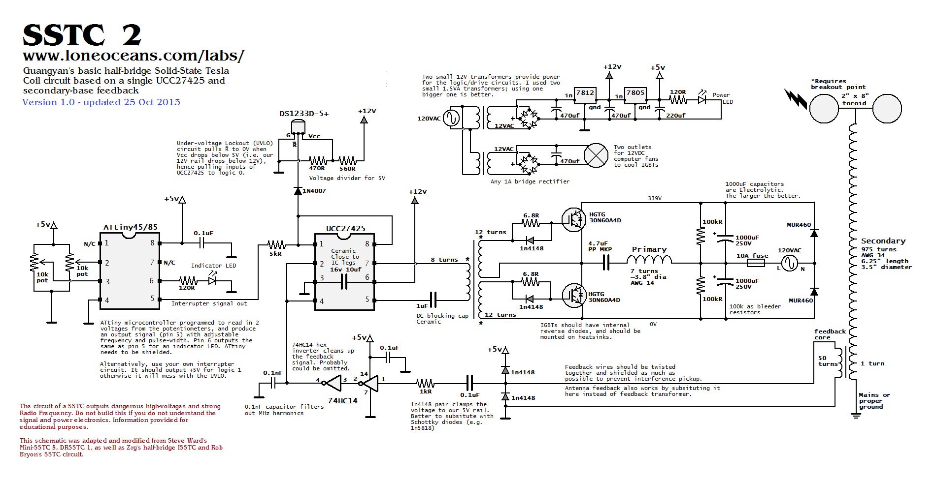
SSTC2 (Small Tabletop Coil) project - which is presented as a complete tutorial on SSTC design, very detailed and well written.  For anyone wanting to build an Solid State Tesla Coil - I encourage you to check out his site (besides the great information he has great photos and video of his coils in action).

I began this project just after the Barnes and Noble Mini Maker Faire, after my first SSTC failed to perform at a second Maker Faire (I had issues not long before at the Chicago Southland Mini Maker Faire). These failures motivated me to make a more robust and easier to transport coil for demonstrations and education.

Current project goals include:
  • solid modular design 
  • modules cleanly attach together (well marked and secure connections)
  • modular components well secured within case (secure but still accessible for repair/trouble shooting) 
  • Indicators and/or test points for each module accessible for inspection/troubleshooting
  • sturdy and clean looking case 
    • Grounded metal case (to shield from EMF generated by coil)
  • Better grounding of  HV side with bypass caps on AC supply to prevent/reduce interference
  • TVS Diodes across MOSFET's/IGBT's to clamp voltage at gates and prevent overloading gates
My first step, as it usually is with my Tesla Coils, is winding the secondary coil.  Not having and 34AWG magnet wire on hand I had to order it and wait for it to arrive (thankfully the company I order from is in Illinois, like me, and their order processing plus shipping time means I only need to wait 2-3 work days before it arrives).
Secondary PVC form cut down and winding just begun


Secondary after stopping to rest (slow going so far)
 This 34AWG wire is by far the thinnest wire I've used so far to wind a secondary (with the exception of a super mini 1.5inch secondary that I made but haven't used yet).  Winding at this point was very slow due to the wire spool rolling away as well as trying to keep winding's lined up (if they overlap I have to unwind and rewind them).
Finally keeping the wire spool stationary
 I finally did the smart thing and secured the wire spool, to speed up my coil winding.
Finished
 For such a small coil, it took a long time to wind (just about 3 hours - not including rest times).

Power and Control Electronics

Half Bridge

Half Bridge

Gate Drive Transformer

Power Supply for Low Voltage Side (5v and 12v)

Power Supply for Low Voltage Side (5v and 12v)

Bottom of etched pcb for Low Voltage Side PSU
 The pcb for the low voltage PSU - etching removed a portion of the trace on the left (bottom) side - repaired with solder bridge.
Controller Board (point to point soldering on perf board)

Feedback Transformer coil
I'm trying out Gao Guangyan's feedback (essentially using a step down transformer) instead of an external antenna.

My coil is not up and running yet (I'm taking my time and making certain that I test each portion before I connect sections together - I've fried enough silicon by rushing things so far).  I've gotten a bit further - so I'll be posting more updates to this project very soon.

Monday, July 27, 2015

Chicago Southland Mini Maker Faire

I finally submitted my registration for the Chicago Southland Mini Maker Faire.
This year I'm building an audio Tesla Coil (or: audio modulated, singing Tesla Coil etc).  I've built a good number of Spark Gap Tesla Coils but my attempts at building a Solid State Tesla Coil seem to result in dead MOSFET's and magic blue smoke.

Saturday, May 16, 2015

Project Theramin - Success... Finally!!!

 I've researched Theremin's quite a but over the past few years, in an effort to build my own.  Theremin's have a distinctive sound and I've always liked it even when I didn't know what instrument made the sound.

I recently completed a Theremin build,  I tried building this particular Theremin 3 times in the past (once on bread board and 2 times on perf board using the wire wrap method), I hayd temporary success on bread board and no success with wire wrap.  I set everything aside for about a year and focused on other projects.  As I got better at building and troubleshooting I came back to finally conquer this build.


This Theremin is based directly on Art Harrisons Minimum Theremin.

 I made a few, very minor, changes to the circuit:
  • Substituted an LM7805 voltage regulator for the one used in the circuit (the pin out is a bit different)
  • Added a power indicator LED
Instead of making this a straight sterile build I wanted to add a bit of style to it. My goal was to make it a bit like a Steampunk version.  As a result, I wanted it to look old and used while still looking fully functional.

Finished Theremin

Theremin Antenna
 It did take me awhile before deciding on the cord attachment to the antenna, after aremad bit of trial and error (and some research) I decided to use boot laces as a jacket for the connecting wire (looks similar to antique braided cloth wire jacketing).
Housing for Theremin
 The box I used to house this Theremin was a simple box from Micheal's craft store.  I removed all the hardware,  remade the front panel, added new "antiqued" brass plated hardware.  Also, sanded, primed, painted and polyurethaned all the outside surfaces. 
Theremin Circuit board

Antenna Connection

Rear of Box


Hooked up to Guitar Amp