Showing posts with label stepper motor. Show all posts

Monday, September 8, 2014

Project 3D Printer - Oh No!!! I released the magic smoke from Arduino Mega and Pololu

Made a lot of progress Saturday on my 3D Printer build. Sunday I focused on configuring the Marlin firmware on the Arduino Mega and getting all the electronic components working correctly:
  • verifying that each axis getting power
  • dialing in current settings on the stepper drivers
  • making sure that stepper directions are set correctly
  • hot end and temp sensor working correctly
I tested using Pronterface (this was my first time using it, checked tutorials later but learned nothing new – the interface is very understandable).
  • able to move x and z axis
    • x-axis moves in opposite direction
      • Inverted the movement direction for x axis in Marlin firmware and now it moves in correct direction
    • z-axis moves but not well
      • increased current to steppers using trim-pot on Pololu board to max current (I did try decreasing also but no movement at all at lower current) and it moves more reliably
  • no movement on y-axis
    • doesn't seem to be getting any voltage – can turn motor with no resistance, even when sending moves in opposite direction.
  • Extruder moves when stepper driver is set at max current but with very little force (light pressure from 1 finger stops rotation)
My main goal Sunday to figure out why the Y-axis is not moving/ getting power. I tried connecting the Y axis motor to the X axis controller (using the original Y axis wiring) and the motor works. Testing the Y axis controller with other stepper motors resulted in no movement. Switching out driver boards – still no movement on Y axis.

To get a cleaner test I removed all wires/plugs/boards from the RAMPS board (including the Arduino Mega) and carefully re-connected everything (or so I thought).  Once I was done re-assembling everything I switched on power to the board and... POOF the x-axis stepper board let out smoke and my computer shut  down.  I instantly cut the power off but I was to late.  On close inspection of the stepper driver board I saw that I had plugged it in incorrectly (2 pins were hanging off the end).  It turns out that not only did I kill the stepper board I also rendered the Mega useless because the USB-to-serial converter on the board got fried, so I can power the board but serial communication is essentially gone.

I guess I've earned another one of these badges http://www.adafruit.com/products/565

I ordered a new Mega board and another RAMPS board (just to be safe since I can't test the one I have).  I think I need a higher voltage PSU to power the stepper motors that I have (minimum voltage for them is 12V) but the  good news is that since I am not using a heated bed my total power requirements are lower that I thought.

Saturday, September 6, 2014

Project 3D Printer - Hope to be up and running calibration prints in the morning

I've been hard at work, with what time I've had, getting this printer build up and running.  Over the 2nd half of this week I've completed the following:
  • Finished X-axis shuttle, (I re-cut it in HDPE but it took awhile since a number of cutting attempts failed)
  • Attached upper brackets for z-axis guide rods and lead screws to upright frame
  • Soldered female headers to end stop wires (had hoped that I had molex connectors that would work but the ones I have are not slim enough to fit on the headers).
  • Designed and cut end stop holders, and secured end stops to holders with #2 machine screws
  • Glued together acrylic for extruder mount to x-axis shuttle and attached to shuttle
  • Designed, cut and mounted drive belt anchor for x-axis shuttle and secured belt to anchor with zip ties
  • Attached bearing mounts for y-axis guide rods to print bed
  • Mounted guide rod supports for y-axis to base of printer
  • Mounted y-axis skate bearing mount for belt drive to machine base
  • Designed, cut and mounted new y – axis stepper motor mount to machine base
  • Finished initial configuration of Marlin firmware
  • Flashed initial configuration of Marlin to Arduino Mega 2560 using Arduino IDE version 0023
I'll be back in the morning with more updates and some actual pictures.

Monday, June 23, 2014

Project CNC and Project 3D Printer - Pictures of current Works in Progress

Progress pictures on CNC mill:
Planning changes in configuration of CNC mill:
     A.) Secure Y-axis directly to base
          1.) designed supports in Inkscape
          2.) need to finish in Makercam and cut out the new pieces from HDPE cutting board
     B.)  Change "waste board" to Poplar board leveled to machine with T-Slot rails for securing
           work pieces, will need to route areas for the rails to fit flush to the leveled board.
 
T-Slot pieces with 1/4" screws and Thumb nuts for workholding
Progress on 3D-Printer Build:
Left side of Z-axis

Left side of Z-axis with stepper and linear bearings

Top is Lft, side of Z-axis, middle is X-axis shuttle, bottom is Rt. side of Z-axis
Overall Frame
Cuts made in bottom of frame to allow travel of Y-axis and Y-axis belt
Cuts in frame, in above picture were done by hand with a Pull Saw (sawdust from cuts still visible).

Left side is initial test cut, Right side is corrected dimensions
 In trying to design a direct drive feed to my printer hot end I ended up having to take an experimental approach.  Initially I designed and cut what I thought I needed (using Inkscape and my CNC machine) and after test fitting and a few redesigns I came up with the part on the right (3 separate layers fused together with M.E.K.)
With bearing attached


Showing path cut for feeding Filament
 My objective was to have a hole drilled through this piece for filament but due to clearances, stepper shaft length, length of fitting for stepper shaft, bearing size... etc, I ended up having to mill a path through the top layer of the piece deep enough for the filament and then fuze a layer of acrylic over top of the piece.

Showing thickness of piece


How PLA filament feeds through


Bolt ground down to fit against stepper motor


Saturday, May 17, 2014

Project CNC - back up and a new computer

I cleaned old glue off of the motor axle and re-glued it after my last post.  Yesterday I mounted the motor/lead screw and spindle to the machine.

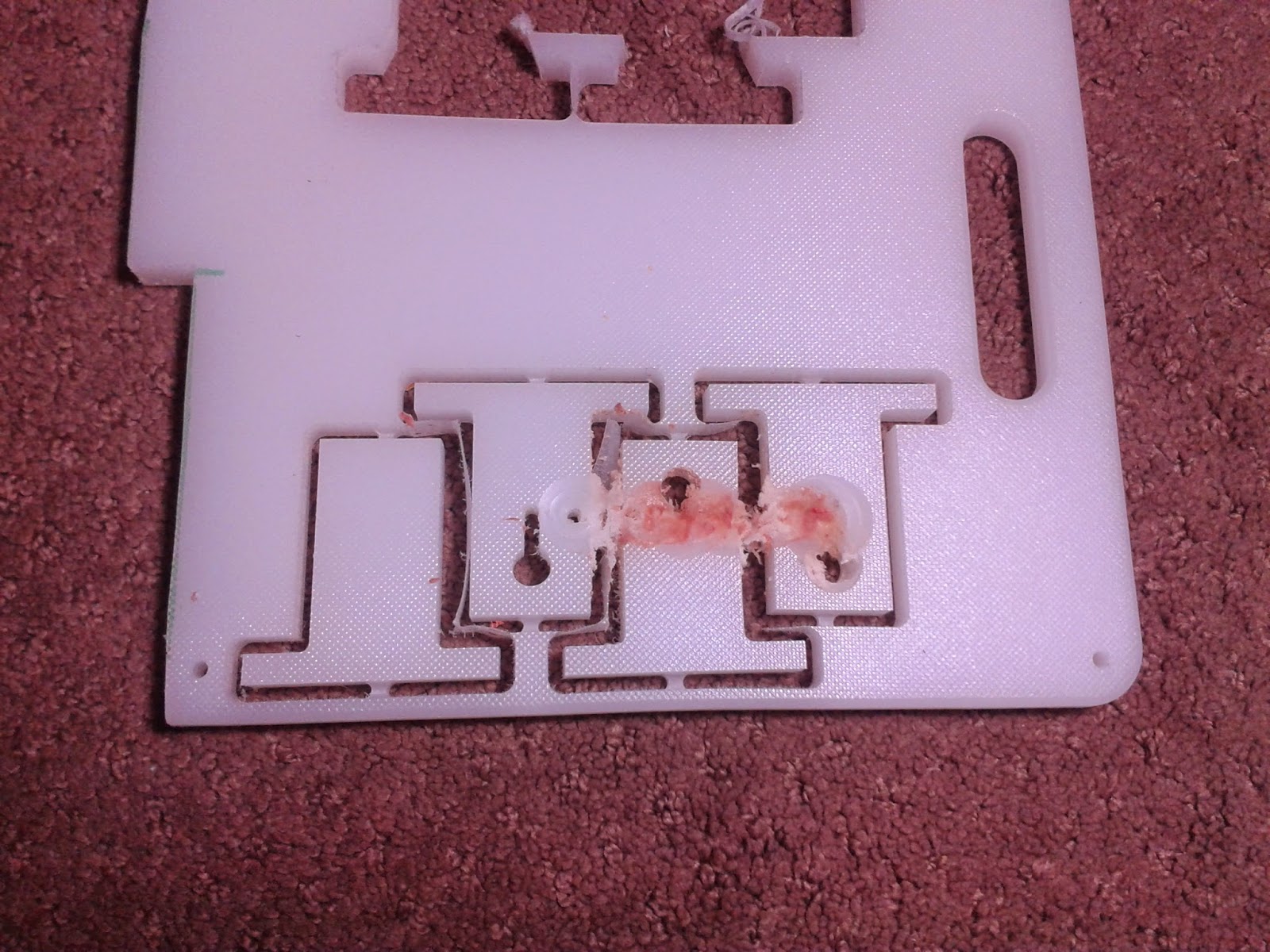
Brown area is where the Z-axis failed

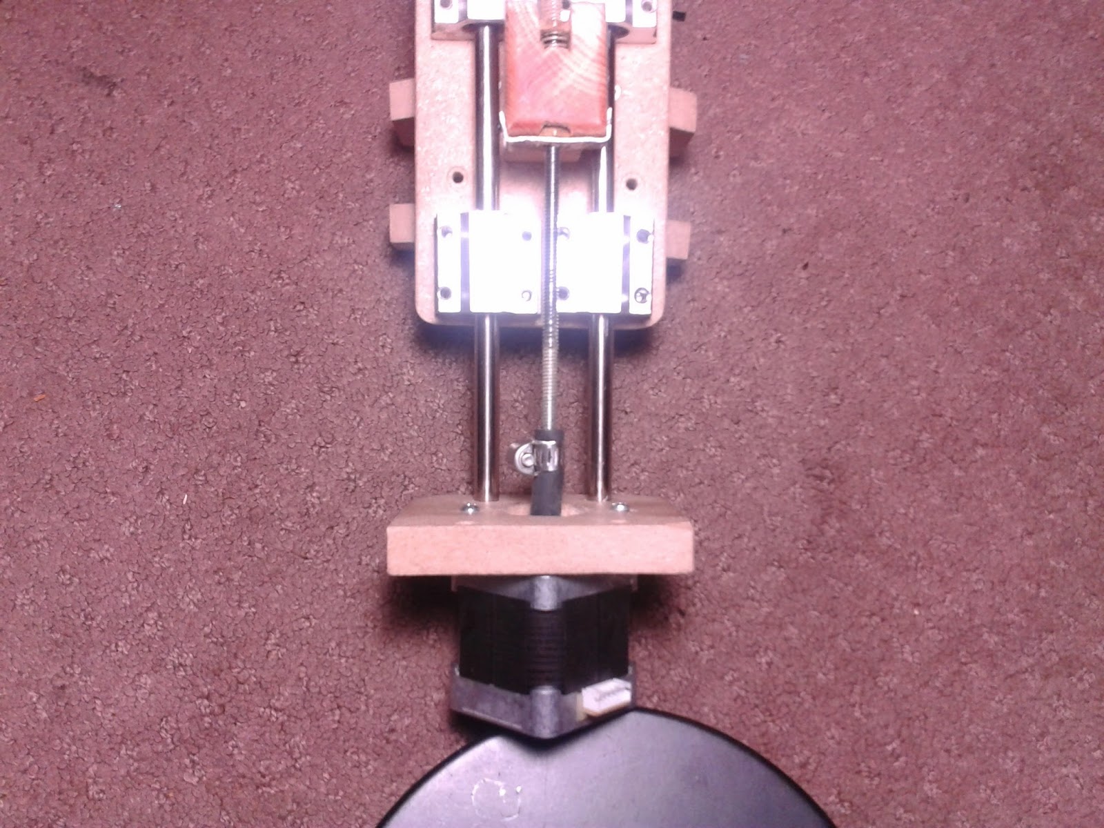
Between pipe clamp and motor tubing came off
 When the tubing connecting the Z-axis to the lead screw separated the spindle dropped down to its lowest limit and the X-axis continued to drag the spindle (I watched it happen and it took me a few seconds to understand what happened and shut off the power).

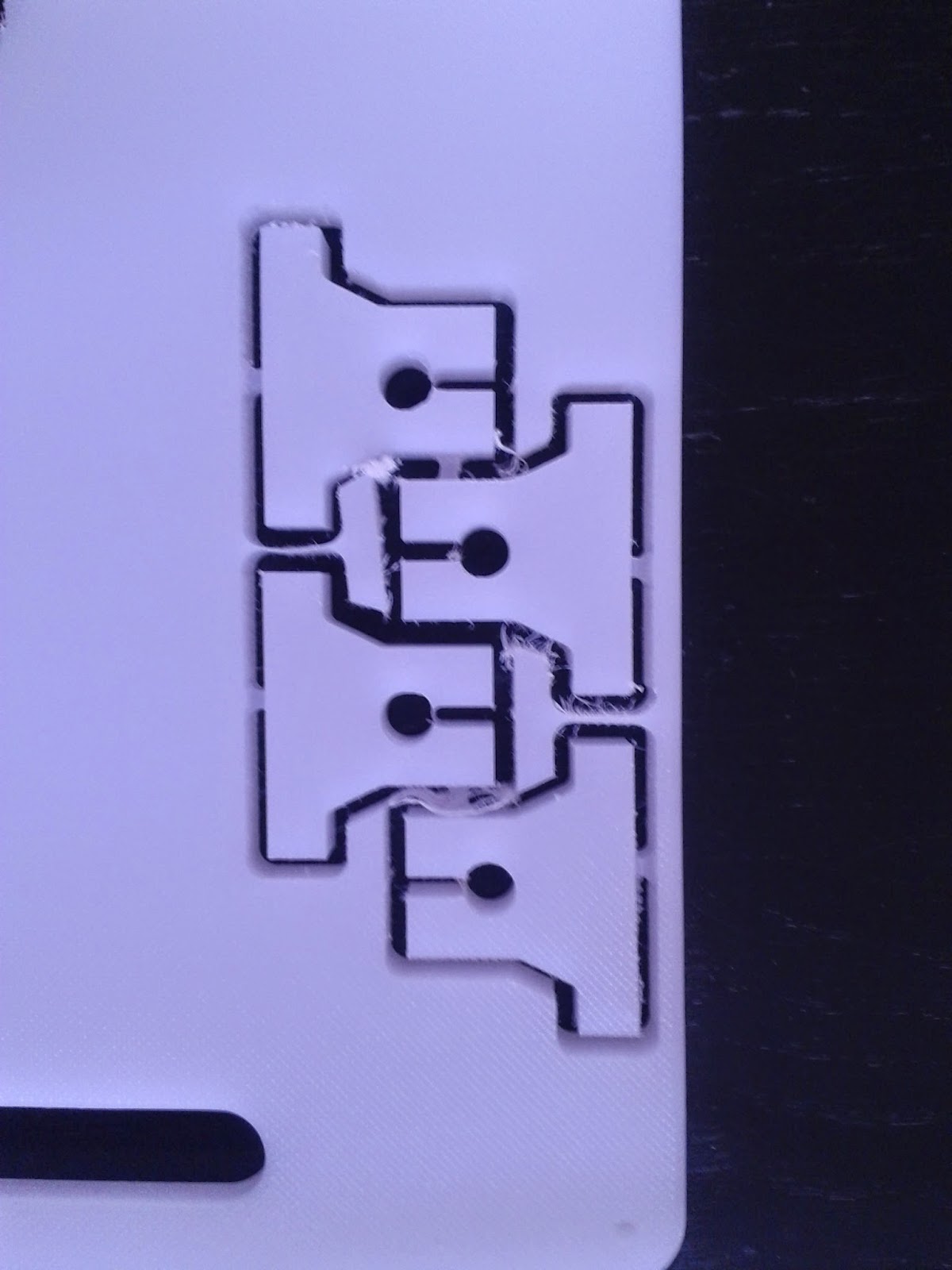
The parts I was cutting were supports for the Y-axis guide rods for the 3D Printer I'm building.  Initially I designed and cut them out of a white HDPE (plastic) Kitchen cutting board but I did not take the stepper motor dimensions into account and they were to short.
Initial guide rod mounts

Mother's Day Present (still working on it...)
Prior to this equipment failure, and subsequent repair,  I was able to do a bit of glass etching with my desktop cnc.  My goal was to make an etched glass edge lit display/sign for my wife for her new Nut Free Bakery (Callie's Cuties).
  1. I did the initial design in Inskape converting image files of the logo etc. (to keep it simple I made sure to use inches for units in Inskape - more on this in step 5).  These then I resized and then used "Trace Bitmap", located under the "Path" tab.  After making sure that everything was converted to a "Path" I saved the file.
  2. After opening a web browser window I went to MakerCAM.  
  3. Before opening my Inkscape ".svg" file in MakerCAM I clicked in "Edit - Edit Preferences".
  4. In the "SVG Import Default Resolution Box" I changed it from "72" to "90"
  5. I then clicked on the "File - Open SVG" and selected the file I wanted on my computer (to keep it as simple and straightforward as possible keep the settings set to inch, in the upper right of the MakerCAM window - if you must use mm you will need a Python extension to truncate the measurements from Inkscape to 4 decimal places, this is automatic in inches, because GRBL cannot handle more decimal places than that).
  6. After my file was imported I did some additional editing (mainly cutting out unwanted parts).
  7. Time to select each object (left click/hold and drag) and then select "CAM - Follow Path"
  8. For each of these I set my depth to 0.01" with a pass depth of 0.01" and plunge and feed speeds at 14.  
  9. After it all looks good select "Calculate All" under the "CAM" menu.
  10. Now it is time to export the G-Code.  Select "Export G-Code" under the CAM tab and save your file.
  11. IMPORTANT: Open your exported file in a text editor and add "%" at the beginning and end of the file (this is not done by MakerCAM but is needed if you plan to use Universal GCode Sender)
  12. The bit I used was a diamond coated dremel bit for glass etching/engraving.  To keep things cool I used a spray bottle filled with water  and sprayed the bit as it cut.
First test piece
 On my first test piece (above), I was checking for an optimal depth with star, square, ellipse and circles for test shapes. The bottom cut was 0.01" one pass, next up was 0.02" in two passes and finally 0.03" in three passes (each pass was 0.01" deep).  In these tests I was using feed speed of 13.  The Cup Cake Character was my next test (using the same piece) and this was made initially from an image imported into Inkscape.  The depth was still jut 0.01" but each line was done with 10 passes, each slightly offset (Inkscape's "Trace Bitmap" has options that result in additional closely spaced lines).


After my initial tests I tried to cut my complete design:
Came out very well, a few traces in the lettering were a bit shallow.  So, testing how it came out with edge lighting I found that I need to etch the image on the BACKSIDE of the glass not the front.  This meant I needed to go back to the images in Inkscape, reverse/mirror them and then run them through MakerCAM again.

In an attempt to make things a little easier I tried building a clay dam around the area to be etched and filling this with water to keep the bit and the glass cool:


Below is my best run, which was messed up by my poor skill in glass cutting (I only taught myself  how to cut glass last week).
After these trials I decided to revert to using Lexan to cut the display out off, instead of glass (the glass never really got bright enough and Lexan is supposed to have better light transmission).


Monday, May 5, 2014

Project CNC - More repairs and learning to adjust current limit of stepper drivers

Early last week I killed the driver board for the Z-axis stepper. Initially, it moved intermittently and then it just stopped moving entirely.  It occurred while I was trying some test cuts in acrylic (to try and find the best feed rate, and depth of cut for different plastics using different end mills/bits). After the Z-axis failed, touching the chip on the driver board I found that it was very hot. I allowed the board to cool (keeping my fingers crossed that it was just a thermal shutdown and would reset when it cooled) and then tried it again... it still didn't work but it did heat up even more.

I expected that I would have a printed circuit board (isolation routed by this very machine) to hold the micro-controller board, motor driver boards as well as plugs for all the connections to power supply, stepper motors, homing switches and control panel – completed by now. But, I don't. While I have finished the board design to plug all the components into – I was so anxious to make the board (a few weeks back) that I didn't wait until I had tested and calibrated everything to the degree that I have now. 
Eagle layout for board to plug Arduino nano, driver boards etc. into
So... initial attempts at making the board failed. As a result I have had to keep the whole deal on a breadboard. My concerns have been that it's way to easy to accidentally pull out a wire and the board is exposed to all the sawdust that is generated when cutting anything (might interfere with connections or even short circuit a connection).
Breadboard with Nano and stepper drivers
Well, early last week one of these possibilities came to light and the result was frying the stepper driver board for the Z-axis.

I have some other driver boards that I pulled and replaced while trying to determine why certain steppers seemed to be missing steps. Initially, replacing the board seemed to help and then the same problem returned. Further testing revealed that the main issue, at that time, was the “Seek” speed.  So, it is possible that some of these "failed" boards are actually Okay

Due to these prior issues I decided that I needed to test and adjust current regulation on all my stepper controller boards (A4988 breakout boards) to help prevent future failures:
  • adjusted all boards to limit current to 1A
    • logic supply to all boards is 5V (Arduino digital outputs)
      Testing and adjusting current limit pot
      • For these breakout boards (A4988) “Vref(in volts) = Current(in amps) / 2.5”
        • measuring Vref:
            • positive voltage measurement so need to take it at test point (using red lead on most VOM's) and reference to ground (black/common lead on most VOM's connected to “-” side of supply – ground pin on Arduino)
            • test point on Pololu board is marked separately
            • test point on other boards (StepStick) is the case of the potentiometer
      • calculating for a current limit of 1A (Current = 1A) we get
        • Vref = 1A/2.5
        • Vref=0.4volt
      • pots adjusted until Voltage read 0.4V
         
  • Tested all boards wired to a NEMA17 stepper using 18v PSU (cordless drill battery) and a super basic Arduino sketch
    • /* StepStick super basic code
      Runs stepper motor 1 revolution each direction

      Digital 3 Step
      Digital 2 Direction

      */

      int Step = 3;
      int Direction = 2;

      void setup() {     
        pinMode(Direction, OUTPUT);
        pinMode(Step, OUTPUT);
        digitalWrite(Direction, LOW);
        digitalWrite(Step, LOW);
      }

      void loop() {
        digitalWrite(Direction, LOW);
       for (int i = 0; i < 200; i++) {
          digitalWrite(Step, HIGH);
          delay(15);
          digitalWrite(Step, LOW);
          delay(10);
        }
       digitalWrite(Direction, HIGH);
      for (int i=0; i<200; i++) {
         digitalWrite(Step, HIGH);
          delay(15);
          digitalWrite(Step, LOW);
          delay(10);
      }
       
      }
  • Determined that I do, indeed, have 4 dead driver boards (2 are from initial tests at the start of this build when I adjusted connections while board was still powered – I'm fairly certain that the most recent board failure occurred due to a connecting wire coming loose on the breadboard).
  • Should be good to go now but I did order an extra 5 boards just in case (I do need, at least, 1 of them for my 3D printer extruder - more on that build later...).

Thursday, May 1, 2014

CNC Mill - demise of another Rotary Tool

Tool Ready for Salvage

Frozen Bearing
In my last post I left off stating that my stepper motors were heating up, squealing and missing steps (what I found was that all this was happening during "Seeking:" movements - fast movements above the surface of the board).

All of this began after I swapped out a few of my stepper motors with ones I purchased for building a 3D Printer (I'll be documenting that build soon).  The newer steppers are also NEMA 17 but are a bit longer - my rational for swapping out the motors was that the new ones should be stronger and better able to handle the weight of the heavier spindle (compared to the weights that a 3D Printer has to deal with - much less).

I approached the issue systematically, looking at possible causes for motor heating, squealing and missed steps:
  • initially thought it must be driver failure
    • testing the the drivers on other motors as well as swapping drivers between steppers in current setup - all drivers seemed fine.
  • poor connections
    • between driver board and arduino - couldn't find any
    • between driver board and motor - nothing
    • between drivers and motor power supply - nothing
  • amperage to high
    • adjusting the current limiting on driver boards
      • this did decrease noise
      • also decreased stepper motor heat
      • Did Not – prevent steppers from freezing up during movements or missing steps
  • step pulse (GRBL firmware settings)
    • I put off testing this until I could look closer at the datasheets for the driver
  • default speeds (GRBL firmware settings)
    • decreasing seek speed seems to have fixed issue
      • decreased to 300 than increased up to 400 and no problems
    • lower current limit seems to be keeping motors (and driver boards) cool
      • 1/8th to ¼ turn clockwise for all motors
    • Other possible answers
      • could be max acceleration instead of max speed


Wednesday, April 16, 2014

Project CNC - Recalibration of CNC X and Y axis

Using a ruler secured the cutting table and an engraving bit in the spindle (90 degree angle 0.1mm carbide bit)
Same type of bit I used (difficult to photograph)

Running the machine with 200mm linear movements in the X and Y axis, I adjusted the settings in GRBL and re-ran tests until I could confirm that settings are as accurate as I can make them with my current equipment.
Finally I thought everything is set up the way it needs to be so I figured I could do some cutting for new stepper mounts for 3-D Printer.  Cuts came out perfect, finally everything came out the way I intended.  But, once I really looked at how I was planning to set everything up, I realized that my mounts would need to be wider (to allow for supports), include screw holes to secure to supports, allow for room/space for the slide bearings on the X-axis.
OpenSCAM rendering of new stepper mount for 3D Printer

I set the machine up, secured the piece to be cut, checked all electrical connections and double checked everything.  Ready...Set...Go... crap!  New Problem - now X axis stepper losing steps in positive direction and motors seem to be squealing and getting hot (especially the X axis motor.

Friday, April 11, 2014

Project CNC - Increasing cut accuracy on CNC mill

New Setup


After some initial test cuts I realized that I needed to replace the sacrificial bed (MDF bed leveled to machine by milling the cutting area to an equal level).  This means that I'll have to redo the whole T-nut setup for work holding.

Leveling out the bed, this time, was pretty quick since I was able to use some wide cut, 1/4" shank, router bits.  I ended up having some issues but in the end I achieved a level bed and cutting this time was about 2 hours - instead of 20!

Issues I had with this bed leveling:
  • when I ran the code (too anxious to do a trial run with no endmill) initial cut started to far in along the x and y axis
  • X-axis lead-screw separated from its connection to the motor in the middle of cutting
    • changed connection to lead-screw back to pipe clamp
  • Z-axis also ended up separating from the stepper while trying to restart bed leveling
    • top edge of rotary tool was bumping into the stepper motor mount for the Z-axis
      • cut mount shorter so that rotary tool is able to move past it
In addition, I ended up retooling the mount for the cutout tool - cutting new brackets out of MDF to secure the tool and moving the mounting spots up 1/2".

After these fixes I ran some more test cuts of mounts for stepper motors that I designed in Inkscape and generated G-code for in MakerCAM:
Progressive improvement in cuts
Earliest cut is the upper left and more recent bottom right.  Cuts are progressively better, in the first row circles are uneven but improving due to changes in cutting parameters (feed and plunge speeds, as well as cutting direction).  Bottom row more significantly improved due to stiffening up the supports for the x and z axis.
Added support for x and z axis
While watching cuts and checking the stability of the machine I realized that there was too much wobble in the supports for the x and z axis (vertical supports).  As a result, I ended up adding steel angle brackets to the vertical supports and when there seemed to still be to much wobble I secured these supports to a large square of plywood.  This seemed to fix the problem which why the bottom row the cuts all look much smoother.

All seemed perfect... until I tried to use one of the brackets with a NEMA 17 stepper and the mount was way to big.  I re-checked all my measurements for designing the mount and it seemed that I had done everything right.   Continuing to research a solution I found that I didn't realize that I needed to change the Default Resolution for imported ".svg" files - automatic default is 70DPI but it needs to be reset to 90DPI for Inkscape.  Below shows a comparison of the results of the 2 settings when using a file imported from Inkscape:
70DPI on left - 90DPI on right


Much better cut with new settings, though you may see a deviation in the larger circular cut on the right at the top.  This deviation ended up being one of my next problems - the z-axis guide rails were backing out of their mount pockets.  For a quick and dirty fix I wrapped the tape around the z-axis guide rails and their supports.  So far this has helped a lot (if you look closely at the first picture you'll see the white tape).

On to the next issue - everything looked great but when I tried to secure a stepper to the mount I found that now the dimensions were just a tad too small.  So... now I'll go back to recalibrating all the axis (I did swap out all the stepper motors with ones I ordered off ebay to build a 3D Printer - they ended up having higher torque than my initial motors and I'll now use them in my 3D Printer build since they won't have to as hard as they did in my CNC mill).


Monday, March 31, 2014

Project CNC - Success

Finally a successful cutting operation!!!  See below for a picture.  Used Inkscape to generate text image and imported vector file (.svg file from Inkscape) to MakerCAM to generate tool paths and G-Code tocut out pockets for the letters.

I used the following instructions to make this (making the letters pockets instead of the area surrounding them).
 

Saturday, March 29, 2014

Project CNC - RIP for the Rotary Tool

Parting out Dead Rotary Tool

I was finally able to get my desktop CNC mill to run well enough, with a new carbide end mill, to finally level out the bed. First, though, I had to replace the bed I thought was MDF with actual MDF (turned out that what I thought was thin MDF was really Hardboard which does not mill well).

I generated G-Code to level the bed with SketchUCAM and then fed it to my mill using Universal G-CodeSender – and it worked great. Well...., except for setting my feed speed and depth of cuts poorly (I set it up for multiple passes cutting down only 0.5mm each pass, down to 2mm – so at least 4 passes). Leveling the bed ended up taking about 20 hours – due to my not optimizing my settings but since I was in bed sick I wasn't too concerned.  After the leveling was done I was able to cut out a layered pocket for milling PC boards (I put it in the upper right corner of the bed).

Since I finally had a flat and level surface to work from I figured I could start cutting out some 2D shapes: stars, squares and circles.  These ended up working fine (can't find my pictures though).

Finally, I thought, it's time to cut out something real.  I decided I'd cut out some 2D figures for my daughter.  Surprise --- my $15 "Tool Shop" Rotary Tool finally gave up. Even after completely dis-assembling it (cleaning all dust and corrosion, at least twice) I finally gave up trying to repair it. I eventually realized that my hours of work, trying to repair this tool, are worth more than the $20 cost of a new tool for the spindle. So... I ended up buying a "Cut Out" Tool from Harbor Freight. After discounts and a coupon it only cost me about $18.  It is a bit larger, heavier and more powerful (3.2A instead of 1.5A).  So, as a result, I've had to modify my tool mount to fit the Cut Out Tool.  At present it is holding steady (with the help of a few zip ties - I am currently re-designing the Z-axis to make it stiffer/more stable and allow more travel).
New Tool - Chicago Electric Cut Out Tool

Work Holding:
Not wanting to have to keep putting screws into the bed I wanted a way to secure materials so I could mill them without the piece moving or being dragged by the end mill. Tape definitely didn't work, push pins didn't work, couldn't find any clamps that would work (tried binder clips, etc). I finally settled on using T-Nuts on the bottom of the MDF bed. This, of course, involved making holes through the bed, as well as countersinking holes on the back side of the bed for the T-Nuts.
  • T-Nuts #6-32 screw size
  • 7cm x 7cm grid 

T-Nuts (counter sunk in bottom of waste board)
 
Top of leveled waste board
 Currently every thing is working as it is supposed to.  I writing some G-code to callibrate the steps per mm for each axis as well as determining the optimal feed rate and depth of cut for MDF and Acrylic.

Monday, February 10, 2014

Project CNC - Start of Build, Materials


An overview of the materials I've used in my build as well as some the rationale I used for my choices.

General Structure
  • 1/2” MDF – 2'x4' piece was about $6.

Motors:
  • Initially I hoped to use ones from old printers and scanners
    • First problem that I ran into was that most of the steppers I've salvaged were unipolar and I needed bipolar motors
    • Next – motors were could not produce enough torque
    • Last – the steppers that I salvaged were all fairly low resolution (about 50 steps per revolution and I wanted more in the range of 200 steps per revolution).
  • Decided on 3 x NEMA 17 (picked up on ebay – they came with vibration dampeners which was a nice extra).
  • Spindle Motor
    • Old cordless Dremel (10-12 years old). When the battery pack died I removed the motor and eventually remounted it in PVC piping along with power cord and a toggle switch to control direction. The shaft on the motor has a rotary bearing and collet holder already attached. This is the motor I used in my initial prototyping.

    • Expanded to using a knockoff brand rotary tool (Toolshop – picked up on sale at Menards for about $15).


Guide rails (rods):
  • From the start I thought of using the steel rods out of printers and scanners
  • I've kept old ones with the idea that I could use them for something someday (they are precision machined).
  • Only issue was that I found that I had 3 different diameters 6, 8, 10mm.
Decided on the 8mm rods since they seemed to be a common size for linear slide bearings when I did online searches.
Initial Y-axis frame with 8mm guide rods

Searching through my salvaged parts I determined that I needed at least 2 more 8mm hardened steel rods. So...I made a trip to Goodwill (with a small section of rod in my pocket to compare) and purchased a a few old scanners that I found ($2-3 dollars each – plus they contain Cold Cathode Fluorescent Tubes, with the boards to power them, additional stepper motors, glass plates, tactile buttons, as well as other goodies).

Currently I am waiting on some additional 8mm rods that I ordered off of ebay (since I decided to use a full size rotary tool for my spindle I wanted to enlarge the size of the work area). When they arrive I should have a work area of about 8” x 13”.

Linear Slide Bearings:
Due to my using 8mm rods for guides I decided on using SC8UU Linear Slide Ball Bearing Block Bearings (this was based on them being the most common slide bearings for purchase – on ebay on other sites). I did do searches for 6 and 10mm slide bearings but they were less common and more expensive. In addition; I wanted “Block Bearings” since I could secure them easily with screws.
Bottom view of Y-axis - square blocks are the linear bearings

Screw Drive vs/Belt Drive:
Initially I intended to use screw drives for the x, y and z axis – later I switched to thinking about using belt drives with gears and belts from old scanners for x and y axis (after reading an article on ebay). After looking at all the different belts I have (and gaining a better understanding of sizes, pitch, spacing, etc. - which came about from my research on what other people have used, why they used it and what is available) I realized that I don't know what belt came with what gear system – I salvaged them from old printers and scanners but did not keep each set together.

Further research lead me to switch back to using a screw drive, since I could use use regular all-thread rod with some additional elements to reduce backlash. In addition I did the math – 24 turns per inch comes out to about 1mm per revolution and with my stepper motors that is 200 steps per revolution or, about, 200 steps per millimeter which should be plenty good resolution. 

I continue this overview in my next post and then get into the nitty gritty of the build process.

Friday, February 7, 2014

Project CNC - Adventures with CNC milling

My First Functional Prototype
I have been looking at home 3D printers and CNC milling machines since I first heard about them a few years ago (I actually heard about 3D Printers first and in the past year learned about home CNC milling machines). 

I knew I really wanted one, but had to focus on what I wanted it to do.  The list of things that computer controlled mills are able to make is very long as the materials they can make them with is also long.  To approach building one I had to be realistic so I needed to answer some basic questions:
  1. What materials do I want to use the mill to work with?
  2. Types of objects I want to make?
  3. Size of objects?
Price is not really a question - I want to minimize it as much as I can but I'm willing to pay more in the long run (during building process) as long as I'm learning how it all works and each purchase I end up making isn't to high.  Basically, I want to keep price low but I'm willing to start simple and cheap and build on what I've made as long as the basic framework is good and solid.  (I've always taken the same approach to other things - like bikes: as long as I have a good frame I can keep improving it with better pedals, tires, bearings, gears, shifters etc.).
A quick note - if you are looking for a quick start into computer controlled milling machines - as in getting one set up and running with minimal hassle I suggest looking at ShapeOko or Phlatprinter (more expensive).  Kits like these will save you a lot of headache - they are tried and true designs.  If you are a bit more adventurous and willing to purchase individual pieces on your own: Mantis 9.1 CNC Mill (mainly for PCB manufacture) is likely the least expensive entry into CNC milling (as long as you substitute stepper drivers with StepStick and use  GRBL  loaded onto an Arduino board - both of which I ended up doing).

I've already spent the past month building, changing things, and building again (repeated many times with different parts of the machine - and I'm still not done all the way).  I will try and bring my build process up to date on here as quick as I can over this coming week.  So, keep tuned in.