Showing posts with label cnc. Show all posts

Thursday, June 25, 2015

Project Edge Lit Sign - PART 2

The Electronics

This part of the project took me a bit longer than I expected.  I thought I had everything figured out for the design, parts and programming for the micro controller (Arduino Pro Micro) but ran into an unexpected issue that forced me to change course and use completely different hardware along with software libraries I hadn't used before.  Good news is that even with the changes and learning new hardware and software the new setup is actually easier and simpler to wire up and use.

My initial electronic design for controlling RGB LED's for the sign illumination.
Parts:
  • 5mm RGB Common Anode LED's 
  • TLC5940 shift registers 
  • Arduino (Nano on breadboard)
  • Resistors for setting current limit
I built up the circuit on a solder-less breadboard to get it working.  Below is the setup from the Arduino Playground.

Wiring for TLC5940
Pictures of the layout:

I transferred the circuit to perf board (laid out the same as solder-less breadboard), cut and drilled out a piece of wood to mount the LED's in my box and wired in a wall wort for power.

All the Parts
Perf Board (back side)
 
Wiring it all up
Software library, further instructions, etc can be found at:
  1. Direct link to Google Repository
  2. Arduino Playground page for TLC5940
 So, after all that work building and testing - it worked perfect but it just wasn't bright enough for the sign so I had to reboot and go a different route.

Decided to go with Neopixels - much brighter RGB LED's.  Individually addressable for color and brightness, much easier to wire up - just a 3 wire connection to Arduino (Trinket or clone).  Do need real basic power filter (1000uF 6.3v or higher electrolytic capacitor across power rail to filter out spikes) as well as current limit to data line (300 to 500 ohm resistor to keep current at set level).

Currently there are 2 very good libraries (that I know of) for controlling Neopixel's with an Arduino.  I provided links to them as well as guides to using them below.

FastLED
Adafruit Neopixel
I'll complete this post tomorrow (Part2b) with the final electronics and code.   

Wednesday, May 20, 2015

Project Edge Lit Sign - Trying Edge lit Sign Again, PART 1

Revisiting my Edge Lit Sign project.  I'm dividing this up into 3 segments due to the separate challenges that I encountered working through each part of this project.  This segment addresses just the engraving of the sign, other segments will address the electronics and mounting/housing.

Many, many people have made acrylic signs illuminated with LED's on the edge.  Adding illumination to the edge of the acrylic causes it to light up only in the areas that it has been cut or engraved. I've previously tried this using window glass engraved using diamond glass cutting bits – it didn't end up being very bright (turns out acrylic transmits light better than glass).

With my 3D Printer build last summer, I shelved this project until I had the time to come come back to it and that's what I'm finally doing.  Instead of etching glass, this time I'm trying it with acrylic that is custom made for edge lit signs (it is clear but has metal flakes embedded in the acrylic that reflect light when the acrylic is cut), you can find it over at Inventables.

I was inspired to do this sign project as a gift for my wife, she owns and runs a nut free bake shop (Callie's Cuties) and I wanted to make her a fun sign for inside her shop with her logo on it.  After getting a vector file of her logo, I opened it up in Inkscape (an open source vector editor).  I only changed a few parts of it to make it a little more friendly for engraving on my CNC (primarily different fonts).  When I finished my changes I selected the whole graphic and made certain to change it all to a Path (selected Object to Path in the Path drop down menu), then I flipped it to make it a mirror image and then rotated it on its side (to fit the dimensions of my CNC).

After working out the size and layout of the sign I made a cardboard mockup to better visualize what my goal was.
measuring and cutting out the cardboard

Reversed image to be engraved (should have used normal image)

Checking image against acrylic stock

Assembling the base

Finished base

Mockup Done!
After reviewing this with my wife, I needed to make a few changes - adding "Open" and "Bake Shop".  So, the orientation changed and the sign became 8" wide by 10" high instead of 9" wide and 8" wide.
 
On to my first hurdle, figuring out the feed rate and depth of cut took a bit of trial and error, I'm using a 1/16" single flute end mill by Kyocera (purchased from CarbidePlus).  Initially I thought I would need to cut fairly deep into the acrylic cut so my first try was cutting to 0.1" depth (almost 1/2 the thickness of the sheet) with a step down of 0.05" (so 2 passes to reach target depth).  First test at 30 in/min was much to fast, I lowered to 20 in/min - still to fast, and then to 10 in/min.  Now that I had a good speed I needed to adjust the cut depth for each pass, 0.1" was definitely to deep, it resulted in to much friction and the end mill getting clogged with melted acrylic.  In addition to that, I felt I was aiming much to deep for my target depth.  I decided on another trial at 8in/min, 0.01" target depth with step down of 0.005".  The first pass achieved the results I as looking for.

I changed the cutting parameters in MakerCAM, selecting the entire graphic and using the "follow path" on the CAM menu: tool size 0.0625", depth of cut 0.004", safe height 0.25", step down 0.004".  After saving the new G-Code file I placed a new piece of acrylic on the bed and ran the code through Universal G-Code Sender.  You can see my result below.

Milling the Reversed Image

The finished image (before cutting extra stock off)

I should note that in my impatience I wasted a sheet of custom acrylic but trying to cut first before determining optimum speeds and depth for my CNC.

Monday, March 16, 2015

Project 3D-Printer and Project CNC - An Update - FINALLY

My DIY 3D-Printer is fully functional (in case you haven't seen my twitter posts).  If you want to check out recent prints or files you look at my stuff on My Thingiverse Page.
State of printer 3/16/15
Changes and additions I've made to my 3D-Printer since September 2014:
  • PCB heated bed
  • moved from single PSU to 2 PSU's needed a separate one to supply the bed heater
  • Relay board added to switch bed heater on.  Pulled signal from gate pin of MOSFET on RAMPS board and wired to a switching transistor and relay
  • Increased to full size bed (250 x 250 x 300mm)
  • Switched to DRV8825 stepper driver boards (produce less heat as well as handle higher current)
  • Hot End - began with a J-head lite, switched to J-Head, now using the E3DV6.
  • Numerous iterations and re-designs of my direct drive extruder
Changes/additions planned:
  • changing all axis to 1/4" - 16 Acme thread rods (feel like it is more dependable since belts need to be checked a lot to ensure good tension)
CNC is finally rebuilt and running.   GRBL updated to version 0.9, Universal-G-Code-Sender updated to version 1.
CNC rebuild 3/16/15

Work on CNC left to be done:
  • calibrate x, y, and z axii
  • mount skate bearing to hold lead-screws on x and y axii
  • add lateral stabilizing to spindle mount
  • enclose and mount control board and PSU
I am now tutoring/teaching math at the Joliet Montessori  Adolescent House and tutoring math a few days a week at the Plainfield Mathnasium.

Monday, September 15, 2014

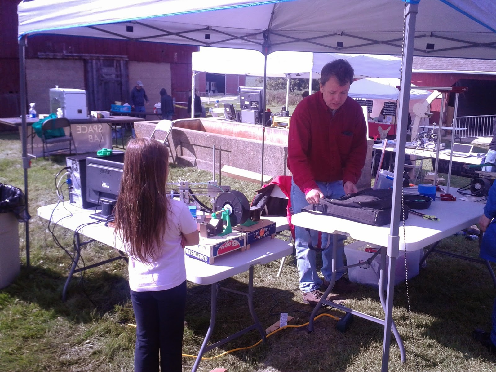
Mokena Mini Maker Faire Pictures

I don't have many pictures and I actually didn't think about taking any until everyone was beginning to break down.  Actually, some exhibitors had already packed up and left, along with the crowd we had earlier in the day.

The day turned out to be great, though it started out cold and windy in the morning.  Steadily, more and more people came out to the point of being pretty busy and the day pretty much flew by.  I learned a lot talking to other exhibitors as well as from people who came to my booth.

I can't wait till next year.

Pictures below: (first pic is my little booth, with Callie hidden behind my desktop CNC)


Links for some other articles and websites about the 1st Annual Mokena Mini Maker Faire:
I wish I had gotten more pictures earlier in the day so I could have caught everyone there as well as all the other exhibitors that I missed (you can check out a list here)

Saturday, September 13, 2014

Updates up tomorrow - 3D Printer, Desktop CNC, Maker Faire

I've been so busy, between working and, trying to get my 3D Printer up and running I haven't had any time to post  (other than on Twitter).  I'll be updating on my build progress along with pictures from today's Mokena Mini Maker Faire (where I exhibited my DIY Desktop CNC and 3D Printer builds)

Sunday, August 31, 2014

Project CNC making parts for Project 3D Printer

Successfully installed new lead screws, new bed and new spindle mount on my CNC. Did a rough calibration of the x and y axis, manually leveled the bed and then fine tuned the calibration for all 3 axis.


My top speeds for x and y axis are fairly high but z axis is still the limiting axis. Any faster than about 14in/min and the z-axis stepper squeals and stutters – resulting in a lot of missed steps. After a bit of research I found a few issues that may be causing this:
  1. stepper motor resonance
  2. lead screw (likely to be less of a problem when I change to acme screw on z-axis)
  3. GRBL
Some good links on this issue:

It looks like I won't be able to get faster moves until I finish my rebuild of the frame and spindle mount/carriage (including swapping the z-axis lead screw with an Acme screw). I have tried tweaking the acceleration and max speeds but when I push it a bit for better performance the Z-axis seems to loose steps when retracting resulting in a number of pocket cuts being to deep.

Finally done with both sides of the Z-axis on the 3D Printer and will be cutting out the X-axis shuttle

Cutting X-axis shuttle tonight, tried this afternoon and GRBL stalled (first time ever).  Already re-cut acrylic for mount for extruder out of acrylic.  Lining up printer bed on Y-axis and designing cuts for securing drive belts on X and Y axii.

Monday, August 25, 2014

Project 3D Printer - Challenges with 3D Printer Continue

Challenges continue with cutting out z-axis pieces for 3D Printer Build.

Autodesk's CNC Utility issues:
  • Step Over is opposite in rough cut and finishing
    • 25% Step Over in rough cut = 25% of width of present cut overlaps last cut
    • 25% Step Over in finish cut = 75% of width present cut overlaps last cut
  • Feed rates
    • in inch/sec but actually inch/minute
  • Initial positioning includes cutting diagonal swath through material
    • manually edit out
Current cuts – contoured portions are not cut down to depth or the width that they need to be (about 1mm short for each dimension), even after x-axis finishing cuts (the finishing cut did increase dimensions somewhat but still not to design dimensions).

14.11 after x-finish 13.54mm before (design goal was 15mm, so still a bit small)
7.25 after x-axis finish cut, 6.19 prior to cut (still short of design of 7.5mm)

Profile cuts (all the way through) and “Cut Out” instead of “Carve” cuts (for straight right angle z-axis cuts) seem to be right on.  I really do not know what the problem is but time is short.

Well...its back to MakerCAM for now and I'll have to stick to square pockets instead of contoured ones (I could do nested pockets but I expect that I'd run into others issues if I tried that).

My main issue with Inkscape to MakerCAM is that shape dimensions in Inkscape end up slightly smaller when imported to MakerCAM (and I don't mean the settings for SVG import resolution – I already encountered and found the simple solution to that issue – change to 90px/inch). When I go the alternate route of OpenSCAD to Autodesk's CNC utility – a cut out 9mm square is actually 9mm. The result is that I have to run test cut dimensions to find correct dimensions for what I design in Inkscape. Does anyone else have this problem??? For me, at least, this seems to be an issue with the SVG file since the cut depths that I enter into MakerCAM do measure out as what I entered in.

On the bright side, at least I already have the Inkscape files for the parts I'm cutting out (since I made and used them to cut the same parts from wood). I still need to re-do all the tool paths in MakerCAM.

It's taken me awhile to get the tool paths correct - first issue was that I had forgotten to include pockets for the  X-axis guide rods, then I did not comprehensively preview an operation in OpenSCAM and missed the drill holes being set to 0.75" instead of 0.5" (extra stress on the Z-axis stepper and burned off half the collar on my endmill).


Test Cuts Autodesk CNC Utility

Test Concave Cut Autodesk CNC Utility

Test Cut Size Check With Inkscape/MakerCAM

This is what I'm aiming for


First Test from Autodesk CNC Utility
A few of my trials from Inkscape/MakerCAM
 After all this work it seems the bed of my CNC is not level, like it used to be - depth of cuts is not consistent across pieces.  Since I need to put a new sacrificial bed on the CNC and add some additional anchor points to hold it down better - I figured that I'd also finally change out my Lead Screw's.  I've had new Acme Thread (single start) 1/4" lead screws for well over a month but put off installing them. 
Old Lead Screws with Anti-Backlash

New Lead Screw- gluing Anti-Backlash
 I decided to change out my lead screws so that I can speed up my cutting procedures - currently the top speed that my CNC travels is 14"/min.  This is because the threaded rods I was using for lead screws had 24 turns per inch - my new acme screws are 14 turns per inch.  My GBRL settings for the threaded rods were about 200 steps per mm - potentially very high precision (current configuration not stiff enough though) but this meant that I could max out stepper speed fairly quickly.  In the future - if I can come across some reasonably priced multi - start acme screws I will have to pick them up.

After I get these screws in tonight, along with a new bed - I'll get the machine re-calibrated for the X and Y axis then route the bed to make it level.


Wednesday, August 20, 2014

Project CNC and Project 3D Printer - challenge using CNC to make parts for 3D Printwer


I am trying to produce some 3D (or at least 2.5D) cuts on my home-built desktop CNC router with the goal of producing better (tighter tolerances) machined parts for my 3D printer.

So far I have primarily used Inkscape (for drawing out parts), Makercam (for generating tool-paths), OpenSCAM  (for previewing cuts) and MS Notepad (to edit the Gcode).

Currently my main issue is that I cannot produce contoured cuts into material using Makercam. I am comfortable designing this type of object in Sketchup but have not been successful in generating gcode and toolpaths from my resulting diagrams.

I've worked through a good number of tutorials for Autodesk's 123D-Design and TinkerCAD, as well as FreeCAD and FreeMill but have not quite found what I want.

My main issues:
  • difficulty or inability to position parts/shapes with precision
  • learning curve too steep and/or online instruction to sparse
  • unclear how to generate gcode for router tool-paths from files generated (can do this with Autodesks 123D CNC Utility but not for other CAD programs)

My current approach:
  1. design parts in OpenSCAD export rendered files as “.stl” and save on computer (be sure to save the openSCAD file for future editing).
  2. In browser open Autodesk 123D CNCUtility
  3. Click on “Start New Project”
  4. Sign in (free to create account)
  5. Select Browse Computer
  6. Open STL file
  7. (opening an STL from your own computer seems to be more reliable and faster than opening file in 123D-Design, saving to “My Projects” in Autodesk's native format and then opening in the CNC Utility or importing directly to the CNC Utility from 123D-Design).
  8. set units to mm (bottom right corner of screen)
  9. In Bottom Menu set:
    1. Under the crossed wrench/screwdriver symbol
      1. Machine to “Shopbot Desktop”
      2. Stock (change this to what you are actually using – may need to use the “add” portion of pull down menu) – change Operation to “Cutout” (instead of “Carve”), add Margin (I change units to mm and make a 5mm margin) -  correction use "Carve" since "Cutout" will not do pockets (only outlines them).
      3. Add “Tabs” to secure part
    2. Under the Drill symbol
      1. choose tool size/type you are using and then choose “add” under “Feeds”
      2. in feeds you need to adjust feed and plunge rates – the utility states the rates in in/sec but is actually in in/min
  10. position part – snap to bottom of stock material (“underlined down arrow” in icons in upper left of screen)
  11. In the last tab on the bottom you can preview cuts
  12. Once you are satisfied with how it all looks click the far upper left file tool and select export tool paths and select folder to save them in (file will be saved with a “.g” extension). - using the "Carve" operation use the rough.g file that is generated.
  13. Preview in OpenSCAM, you will have to open folder and set to view all files (not just gcode files) and select the “.g” file. Examine result carefully – all of my files seem to begin with a 3D diagonal to the deepest point and then back up. To eliminate this open the “.g” file in a text editor and delete the “Z” portion of the first X Y Z move.
 Below is a the start of a ".g" file created from Autodesk 123D CNC Utility Online.  The highlighted area is what you need to delete to correct the file.

;Toolpaths generated with Autodesk 123D CNC Utility Online(Version 1.3.0)
;
;
;Rough Pass Settings:
; Tool parameters :
; Type : End Mill
; Name : 1/8 in Straight (13728)
; Diameter : 0.125 in
; Pass Parameters :
; StepOVer : 70
; Pass Depth : 0.05 in
; Jog Height : 0.25 in
; Feed Rate : 14 in/sec
; Plunge Rate : 14 in/sec
; Jog Rate : 14 in/sec
; Spindle Speed : 20000 rpm
;
;
%%
G17
G21
G40
G49
G54
G80
G90
G94
F330.2
S20000
G00Z6.35
M03
G04 P1
G00X30.34Y31.6929Z-6.35 (DELETE THIS PORTION)
G01Z10F330.2
F330.2

Un-Corrected G-Code

Corrected G-Code
Over the weekend I was able to calibrate my Desktop CNC Mill and tighten up parts of the frame and gantry to make everything stiffer and more accurate/consistent.

Saturday, August 16, 2014

The Countdown to Mokena Mini Maker Faire Begins!!!

3D-Printer Build at Present
After finding out that the Mokena MiniMaker Faire is on for September 13, 2014 I decided that I really needed to attend as an exhibitor.  So... I thought it would be great idea to exhibit the 2 things that I have been working on for most of this year: my desktop CNC machine and my 3D-printer. Both of these machines are home built home fabrication machines which is why I thought my exhibit should be called “Making Machines that Make”.

I figure that signing up for this will provide the extra motivation for me to finish up the 3D Printer and add improvements/fixes to my CNC machine – since there is a definite deadline and people will be expecting to see what I've done. In addition, it should help push me to document my progress, pitfalls, solutions etc. to help others who want to attempt these type of projects.

Wish me luck!

Saturday, June 28, 2014

Project CNC - CNC Controller Board Pictures

Top of Controller Board

Bottom of Controller Board

Assembled Controller Board
Finally posting pictures of new controller board for CNC machine.  It is fully tested and functions great.  Arduino Nano on left of board and stepper drivers in the right.  At least this is one less thing to worry about (motor cables falling off breadboard).

I ordered 1/4" 16tpi Acme screws from McMaster Carr to replace the #10-24 threaded rods that I'm currently using.  I ordered 2 nuts for each axis so that I can make new anti-backlash nuts like the ones I am currently using.  Finally settled on lead screws instead of belt drives because I felt that they would be more likely to be able to handle all the debris produced by the machine (from cutting materials).  Once I replace the lead screws I will need to switch the stepper controller boards to micro-stepping mode to maintain (and improve) resolution.

Wednesday, June 25, 2014

Project CNC and Project 3D Printer - New supports for Y-Axis guide rods (CNC machine)

I originally planned on using the initial supports that I cut for my 3D Printer (Y-axis also) but they were just a bit to short.  My choices were either cut out a pocket for the stepper motor in the base board, add spacers under the supports or just cut new ones.  Well... I just decided to cut new ones, its quick and just as important it'll look a lot nicer.

Both supports (old and new-just cut) were cut from 1/2" thick HDPE kitchen cutting board.  I like the material since is cuts and drills fairly easily, is non reactive to most chemicals, not electrically conductive, and does not shrink or expand with temperature or humidity changes (at least not to any significant extent).

Here is a picture of both supports - the new one on the left and the old one (originally meant for the 3D Printer) on the right.
Both are unfinished.  They both still show the "tab's" added to hold pieces in place while cutting, as well as left over flakes from being cut out.  Even with that it is easy to see the difference in height for the guide rod holes.  In addition, I squared off how the top meets the base to make more room for the mounting scews.


Monday, June 23, 2014

Project CNC and Project 3D Printer - Pictures of current Works in Progress

Progress pictures on CNC mill:
Planning changes in configuration of CNC mill:
     A.) Secure Y-axis directly to base
          1.) designed supports in Inkscape
          2.) need to finish in Makercam and cut out the new pieces from HDPE cutting board
     B.)  Change "waste board" to Poplar board leveled to machine with T-Slot rails for securing
           work pieces, will need to route areas for the rails to fit flush to the leveled board.
 
T-Slot pieces with 1/4" screws and Thumb nuts for workholding
Progress on 3D-Printer Build:
Left side of Z-axis

Left side of Z-axis with stepper and linear bearings

Top is Lft, side of Z-axis, middle is X-axis shuttle, bottom is Rt. side of Z-axis
Overall Frame
Cuts made in bottom of frame to allow travel of Y-axis and Y-axis belt
Cuts in frame, in above picture were done by hand with a Pull Saw (sawdust from cuts still visible).

Left side is initial test cut, Right side is corrected dimensions
 In trying to design a direct drive feed to my printer hot end I ended up having to take an experimental approach.  Initially I designed and cut what I thought I needed (using Inkscape and my CNC machine) and after test fitting and a few redesigns I came up with the part on the right (3 separate layers fused together with M.E.K.)
With bearing attached


Showing path cut for feeding Filament
 My objective was to have a hole drilled through this piece for filament but due to clearances, stepper shaft length, length of fitting for stepper shaft, bearing size... etc, I ended up having to mill a path through the top layer of the piece deep enough for the filament and then fuze a layer of acrylic over top of the piece.

Showing thickness of piece


How PLA filament feeds through


Bolt ground down to fit against stepper motor