Thursday, July 21, 2016

Hackaday Prize 2016 - I'm a Round 3 Winner
I'm so amazed, overjoyed and honored that my Universal Glucometer project actually made the Top 20 of the 2016 Hackaday Prize - Citizen Scientist Round .
I've got a lot of work ahead of me - primarily on the coding side, but I'm determined and I WILL get it done, along with a fully functional prototype.
Here is a list of all 20 Winners of Round 3 Citizen Scientist Round:
I've got a lot of work ahead of me - primarily on the coding side, but I'm determined and I WILL get it done, along with a fully functional prototype.
Here is a list of all 20 Winners of Round 3 Citizen Scientist Round:
- MyComm
- Open Source Arduino Blood Glucose Meter Shield
- CODE RED
- Neuroscience of Grasshopper Jumps
- Flypi – Cheap Microscope/Experimental Setup
- Spectrophotometer
- Alli-GAIT-or Analysis
- Internet Of Things Microscope
- PULSE : Profiling Underwater Light SEnsor
- Affordable Reflectance Transformation Imaging Drone
Tuesday, July 12, 2016
2016 Hackaday Prize, moving into round 4
So far 3 of the 5 rounds for the Hackaday Prize 2016 (this years theme is - "Build Something That Matters") have finished:
- Design Your Concept (March 14 - April 25)
- Anything Goes (April 25 - May 30)
- Citizen Scientist (May 30 - July 11) just finished, no results yet
The top entries for rounds 1 and 2 are listed below:
The top 20 projects of theHackaday Prize 2016 "Design Your Concept" challengeare:
The top 20 projects of the 2016 Hackaday Prize "Anything Goes"challenge are:
- Automatic Digital Microscope (also in top 20 of round 1)
- ICeeData (also in top 20 of round 1)
The Citizen Scientist Challenge (Round
3) just finished yesterday and that marks the start of the Home
Automation Challenge (Round 4), to be followed by the Assistive Technologies Challenge (Round 5) which is the last round before finals.
In the next few days we should have news of the to 20 projects in Round 3, that will be added to the list of the top 100 projects going into the Finals.
My 2 entries to the Hackay Prize 2016 (Universal Glucometer and Train Your Brain) have not yet made it to the top 20 of any round so far ( ;( ), but I continue to work on them both.
Project: Universal Glucometer - in the news (well... sort of)
While trying to show a friend my Universal Glucometer entry for the 2016 Hackaday Prize, I came across this article: Hackaday Prize Entry: A Universal Glucose Meter.
It was definitely a nice surprise, I must have missed notifications in my feeds.
It was definitely a nice surprise, I must have missed notifications in my feeds.
Sunday, June 19, 2016
Project Universal Glucomter - 1st Contact

I decided to take a step back and return to some real basic level stuff for programming and using PIC Microcontroller's. First order of business was to ensure my programmer (PICkit3 clone) actually works and that I can actually upload programs (I know compiling programs works but I haven't actually uploaded anything) . Back when I ordered my last LCD screen (which is actually the wrong one for the reference design from Microchip) I also ordered a few PIC16F877A chips since I have some books that use them for learning to code in C for PIC's.
The first program I wanted to try was the most basic, a simple "Hello World" program that blinks an LED. The tutorial I worked from was Blink LED with PIC16F877A. The first hurdle I needed to make it over was how to actually connect the PICkit3 to the micro-controller (in hindsight, if I had started with a Development Board this would not have been an issue). Bread boarding the circuit was no problem from the schematic:
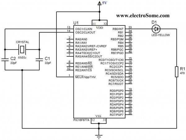
As I put together the circuit on a solderless bread board I realized that I did not order any crystals for the timer oscillator (I'd spent so much time going over the datasheet for the PIC16F1786, from the glucometer reference design, that I never realized that the 877A has no internal oscillator). After going through crystals I scavenged from old electronics, I found a 4MHz ceramic (3 pin, no need for external capacitors) oscillator. I didn't really know if it still worked after de-soldering it from devices and I'm not really sure how I could test it but took my chances and used it anyway.
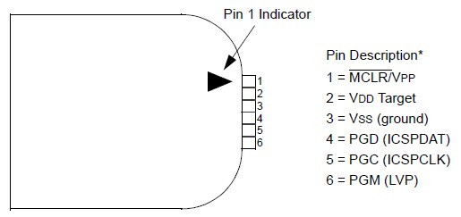
After everything was assembled I needed to connect the PICkit3 programmer. Pin #1 is designated on the connected by a solid white arrow. Pin functions are:
1 = MCLR/VPP
2 = VDD Target (power)
3 = VSS (ground)
4 = PGD (ICSPDAT)
5 = PGC (ICSPCLK)
6 = PGM (LVP)
VDD and VSS could easily have confused me but I knew from prior reading that VDD is + power and VSS is ground. That leaves the other 4 pins - actually 3 since pin 6 is not used here. Referring to the pin out for the PIC16F877A chip:

- 100uF ceramic caps across pins 11/12 and 31/32
- pullup resistor on MCLR/Vpp (pin 1) - around 5-10K
#pragma config FOSC = XT // Oscillator Selection bits (XT oscillator)
My other Configuration Bit settings were:
#pragma config WDTE = OFF // Watchdog Timer Enable bit (WDT disabled)
#pragma config PWRTE = OFF // Power-up Timer Enable bit (PWRT disabled)
#pragma config BOREN = ON // Brown-out Reset Enable bit (BOR enabled)
#pragma config LVP = OFF // Low-Voltage (Single-Supply) In-Circuit Serial Programming Enable bit (RB3 is digital I/O, HV on MCLR must be used for programming)
#pragma config CPD = OFF // Data EEPROM Memory Code Protection bit (Data EEPROM code protection off)
#pragma config WRT = OFF // Flash Program Memory Write Enable bits (Write protection off; all program memory may be written to by EECON control)
#pragma config CP = OFF // Flash Program Memory Code Protection bit (Code protection off)
It's taken me a few days of reading, trial, and error but I've finally gotten an LED to blink (pretty impressive right!).
Next step is attaching and sending text to a standard 16x2 LCD.
If I have to I will stick with the PIC16F877A, but if I do I'll at least need an external Op-Amp connected (to amplify the signal from the strip). Hopefully I'll be able to return to the 16F1786 and won't need to deal with that.
Monday, June 13, 2016
Project Updates
Sorry I haven't updated this blog for quite a while - it's due to working on projects over at Hackaday.
I currently have 2 entries for this years Hackaday Prize.
- Open Source Neurofeedback (click for details)
- Universal Glucometer (click for details)
For my Open Source Neurofeedback project my main challenge continues to be learning to program in Java.
- While I do have experience in BASIC, PASCAL, batch files for MS DOS, some C and just a little Python and am reasonably comfortable with linux command line stuff. While I can read Java programs and understand them, learning to write my own is taking a bit longer than expected. But, I am starting to get the hang of it.
- The hardware side of this project is fairly straight forward, even with a few modifications I've made as I've been prototyping.
My Universal Glucometer project has presented me with a number of challenges:
- While Microchip provides some base code for a glucometer along with a test layout - some parts are no longer available or difficult to find - which goes counter to my idea of a glucometer that can be built from basic parts and adapted to different test strips. Due to these issues I've decided that I need to change code to use a different LCD (the LCD in the Application Note is hard to find - I actually ordered the wrong one -twice - same manufacturer but different pin-out and control protocol). So, if it is a problem for me to find it now, it'll be worse for others later - need to use an easier to find/source display (maybe a standard 16x2 LCD or a Nokia LCD display - both are easy to get cheap on Ebay).
- The biggest challenge I've had is figuring my way around Microchip's Microcontrollers: writing code for them and uploading code. I only recently moved into programming AVR's instead of Arduino's and in hindsight it would have been easier to start with a development board and then worked up to a bare chip (like going from Arduino to AVR's). It took me awhile, but I finally got MPLAB (Microchip's IDE - Integrated Development Enviornment) installed, along with XC8 (Microchips C compiler for their 8 bit microcontrollers). I even got the demo program for Glucose Meter to compile. I am still trying to upload it to the actual microcontroller using MPLAB and PICkit3.
Wednesday, April 20, 2016
Project - Neurofeedback EEG Mindflex to MindWaveMobile Headset Part 2 (Details)
Configuring the TGAM1 board for raw EEG data (57600 baud)
Click here to go to part one

- The default output baud rate for TGAM1 boards (at least the ones taken out of Mindflex and Force Trainer headsets) is 9600 baud (this only allows you to capture data for the default frequency bands once per second).
- To use these cheap headsets with apps made to work with "Think Gear" headsets - we need to change the communication rate to 57600 baud. There are 2 methods to achieve this:
- One way involves programming the TGAM1 board over Bluetooth - if you look through the links at the end of this post you'll find ways of doing this. I did not do it this way, instead I chose the second method.
- The second way involves removing a single SMD (surface mount) resistor (pull-down resistor) and adding a different resistor going from the same area and then over to positive connection of the power supply on the TGAM1 board (pull-up resistor).
- To do this you'll only need:
- Basic soldering iron
- 10k 1/8th watt resistor
- Heat shrink tubing to insulate the resistor
- Step 1: Remove SMD Resistor (surface mount resistor, it a little rectangle on the top of the board.
- The SMD resistor can be removed by heating up the pad with a soldering iron and pulling it off with tweezers (or, if you are brave - snap it off with needle nose pliers).
- Step 2 - Solder in the 10k through hole -(meaning is has wires) resistor.
- the 10k resistor goes from the spot marked B1 on the board and goes over to the positive power connection (refer to the labeled picture at the top of this post)
Setting up the HC-06(?) Bluetooth Host/ Slave Module (SPP – Serial Port Profile).
Setting up the Bluetooth communication board/module:- Configuring the Bluetooth Slave Module for 57600 baud rate (most modules seem to be configured for 9600 baud rate as the default setting) **This step should be done with the Bluetooth Module alone (not connected to the TGAM1 board)**
- This is where we need some type of USB to TTL serial converter
- The easiest is to use an Arduino Board and load a 'Sketch' to connect to the Bluetooth Module over the serial console.
- Breadboard wiring (from Fritzing - just pretend the HC-05 is an HC-06 Slave)

- So, you need:
- An Arduino (I like the Nano since its made for bread boards - but you could use an Uno, etc.)
- Logic Level Shifter
- HC-06 Bluetooth Breakout Board
- Arduino sketch to send commands to the HC-06 (HC-06 Setup ).

- Physical connections of Bluetooth Serial board to TGAM1board pics
- I used 90 degree male pin headers so I could use cables
- Bluetooth RX pin to TGAM1 TX pin
- Bluetooth TX pin to TGAM1 RX pin
- Vcc to 3.3v source (if you are using the Mindwave or Force Trainer headset use the on board regulated voltage)
- Gnd - make sure the TGAM1 and HC-06 (or -05) grounds are connected together
- LED on Bluetooth Module
- When initially connected to power it should blink
- There are different flashing rates that depend on default baud rates
- Vast majority of modules are set at 9600 as the default baud rate
- There are different flashing rates that depend on default baud rates
- LED will stay lit constantly after the device is paired
- actually a little more complicated – stays lit constantly when paired and ACTIVELY sending data to application (while setting up my module, I couldn't understand why it would say it was paired and the light on the board continued to blink. Even after I attached it to the headset and powered it on again – it continued to blink – computer said it was paired. FINALLY, after installing Neurosky's Mindwave Mobile and starting the Brain Wave Visualizer – it stayed lit. After I closed Mindwave Mobile it began blinking again. I mention all this because, I didn't see it stated anywhere else.)
- actually a little more complicated – stays lit constantly when paired and ACTIVELY sending data to application (while setting up my module, I couldn't understand why it would say it was paired and the light on the board continued to blink. Even after I attached it to the headset and powered it on again – it continued to blink – computer said it was paired. FINALLY, after installing Neurosky's Mindwave Mobile and starting the Brain Wave Visualizer – it stayed lit. After I closed Mindwave Mobile it began blinking again. I mention all this because, I didn't see it stated anywhere else.)
- When initially connected to power it should blink
Some REALLY BASIC! Background on Bluetooth Communication
Being very, very new to working with Bluetooth, myself, I decided to include some additional information so that others can hopefully avoid making the same mistakes that I've made:Slave vs Master
- Master is the device at the center of a Bluetooth network (in this case – your phone, tablet or computer)
- a Master can pair with multiple Slave devices
- a Master can pair with multiple Slave devices
- Slaves send and receive data only to or from the Master (in this case – the MindFlex headset, you could, conceivably, pair multiple headsets to one Master device)
- a Slave can only be paired to 1 Master at a time
- a Slave can only be paired to 1 Master at a time
- Bonds Slave device to Master device
- After pairing devices automatically connect when they are both powered on and close enough
- uses authentication data saved on the 2 devices
- uses authentication data saved on the 2 devices
- HSP -head set profile
- HFP – hands free profile
- HID – human interface device (generally a keyboard, mouse, etc.)
- SPP – serial port profile (this is what we need for communication)
- A2DP – advanced audio distribution profile (streaming audio data to speakers, etc)
- AVRCP – A/V remote control profile (Bluetooth remote for TV, etc.)
- First modules I purchased were actually just back planes (essentially just the breakout board without the module – read descriptions very carefully – not a costly mistake but annoying)

- The
next module was a Master – (projects I looked at never seemed to
mention if I needed a Master or Slave module... well it turns out I
needed a Slave module, of course)

- Finally got an HC-06 Slave Module


AT Commands
You can find these on the datasheets for the Bluetooth Serial Modules (you can find them online - none of the ones I ordered included the datasheet). AT commands apply to both the HC-05 and HC-06 boards. These are the ones we need to setup the HC-06 breakout:
- AT pings the device (response back “OK”over serial)
- AT+PINxxx
- AT+NAMExxx
- AT+BAUD4 (sets baudrate to 9600 – default rate)
- AT+BAUD7 (sets baudrate to 57600)
Links to more information and resources:
- Neurosky http://neurosky.com/ http://developer.neurosky.com/ (links to many different hacks)
- http://neurosky.com/biosensors/eeg-sensor/
- http://store.neurosky.com/pages/mindwave
- http://store.neurosky.com/collections/apps
- Development Tools for PC/Mac
- Brainwave starter kit
- http://developer.neurosky.com/docs/doku.php?id=mindwavemobile
- Mindflex/Mindwave Mobile Core
- ThinkGear Connector
- Developer Software
- Mindflex/Mindwave Mobile Core
- http://developer.neurosky.com/docs/doku.php?id=mindwavemobile
- http://neurosky.com/biosensors/eeg-sensor/
- NeuroExperimenter (application) – development site https://sites.google.com/site/fredm/neuroexperimenter
- TGAM1 DataSheet http://www.docfoc.com/t-gam-sales-sheet-20111004
- http://www.instructables.com/id/AT-command-mode-of-HC-05-Bluetooth-module/
Subscribe to:
Posts (Atom)