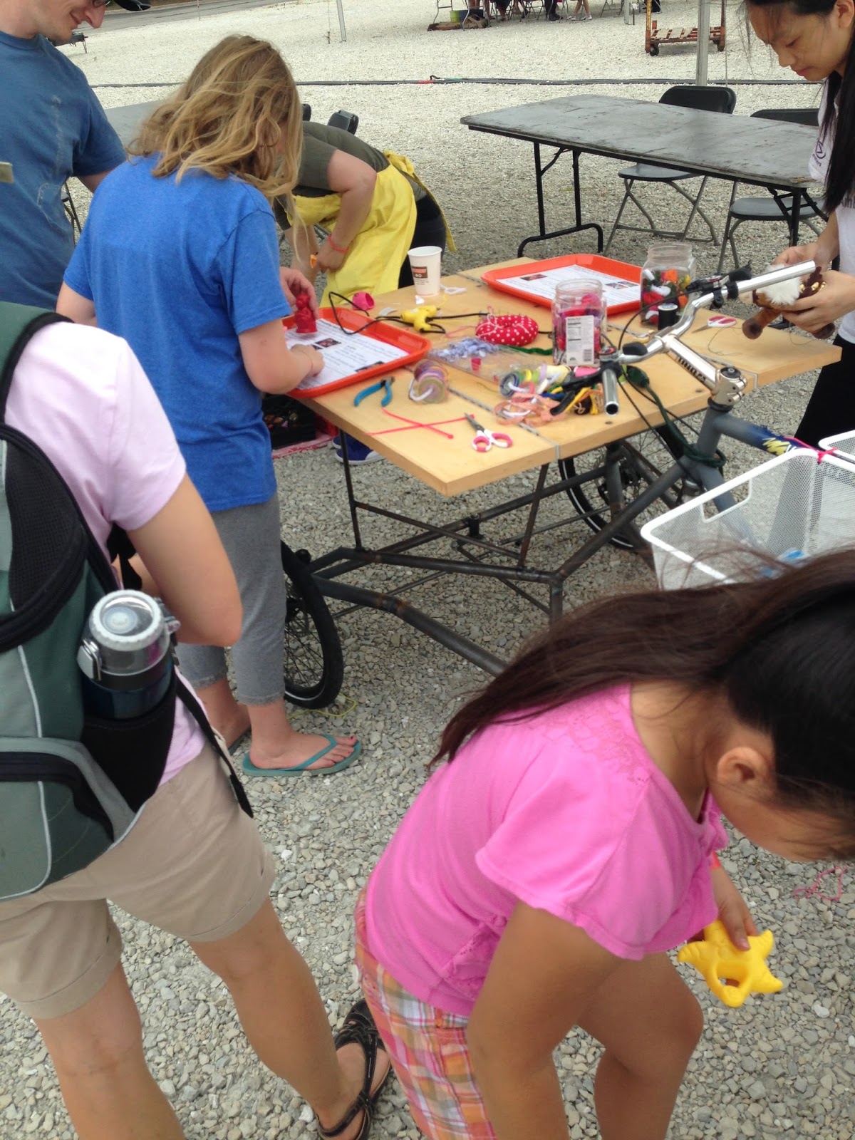
Anyway, here are some photo's of the event:
Wednesday, August 26, 2015
Chicago Southside Maker Faire 2015
In an attempt to catch up from the past month or so, I'm posting a good number of posts over a short period of time, For the first - Chicago Southside Maker Faire was held just a few weekends ago (Aug. 8th) at Ford City Mall. Just like last year, I got lost on my way there (due to me and Goggle Maps). My daughter and I did arrive before noon but only had about an hour to check out everything (not enough time) since I had to get her to a party for her school
Anyway, here are some photo's of the event:
Saturday, August 8, 2015
Project SSTC1 - I've got Sound!!!
After reviewing datasheets, yet again, for the MOSFET drivers I'm using (TI's UCC37321/2) and re-reading some sources on interrupters for SSTCs and methods of audio modulation with SSTC's I finally had that Ah-Ha moment.
I've made Plasma Speakers / Singing Arc's just after building my first Spark Gap Tesla Coils. These, generally took an audio signal (normally fed to a speaker or earphones) and put it through the driver for a Television Flyback Transformer.The only method I used involved amplitude modulation (AM-like radio) and SSTC audio drivers seem more focused on frequency and pulse width modulation. Correction, after re-reading datasheets for the LM555 timer chip I learned that pin 5 actually modulates the frequency (some descriptions I had read stated, incorrectly, that pin 5 adjusted the output amplitude. I finally understood how you combine frequency and pulse width modulation (it's actually pretty simple and involves pretty simple calculations).
I'll get more into the difference later, for now here's the video:
I've made Plasma Speakers / Singing Arc's just after building my first Spark Gap Tesla Coils. These, generally took an audio signal (normally fed to a speaker or earphones) and put it through the driver for a Television Flyback Transformer.
I'll get more into the difference later, for now here's the video:
Saturday, August 1, 2015
Project SSTC1 - SUCCESS AT LAST !!!
Finally, my SSTC (Solid State Tesla Coil) is working. My Driver Board and Interrupter Board have been working fine all along it has just been my high power side - the half H-Bridge board. I have burned out many MOSFET's trying to get the Half H-Bridge Board to work, my last test (less than a week ago) burned out 2 MOSFET's - I think it may have been due to overheating.
After re-designing my H-Bridge Board again and adding heat sinks (cut from an old CPU chip heat sink) and a cooling fan - it all finally works - no overheating, no magic smoke being released just nice plasma from the coil.
Thursday, July 30, 2015
Project SSTC1 - Reviving my Tesla Coils and taking them further Southland Mini Maker Faire
I first saw instructions on building a Tesla Coil back in the early 1980's, in either Popular Science or Popular Electronics magazine, while at science camp over summer break during elementary school. The design used a multiple gap spark gap (copper tubes inside a cylinder - which I now know is a Richard Quick Spark Gap) and capacitors made out of window panes and aluminum foil. It looked Super Cool to me but the concepts were beyond my understanding and the idea of building it was a bit scary (I couldn't imagine who I could ask for help or even just address my questions),
The picture stuck in my mind - I just wanted to see one up close and in person. While on a road trip up the East Coast (early 90's) I saw a sign (it was somewhere either near or in Boston, MA) where they had some big coils that they used for a lightning display. I remember going by the museum to find that the exhibit was closed. Tesla Coils and man made lightning retreated in my mind.
Fast forward about 20 years - While working with my daughter on some basic electronics projects - make a simple electric motor using a magnet, magnet wire, a battery, paper clips and soda straws I thought why not make sparks!!!
I was really thinking about static electricity (I loved being able to shuffle across the carpet so I could reach out my finger to ZAP my brother or sister - they did the same to me of course). So, I thought why not make a Van De Graff Generator.
After building a small one, that did work, just not very well I wanted a more impressive display. A Tesla Coil seemed to be the answer, so I began my research (thinking it would only take a few weeks to build it). Well, it took a bit longer - more like 4 months research, trial and error, failures and finally success.
During my process of building the coil I was showing videos of Tesla Coils (on YouTube.com) to my daughter and we came across Tesla Coils that could play music. That just seemed so amazing, I looked into how people were able to do it. It appeared fairly complicated but I found something I might be able to do - an audio modulated Plasma Arc (or Plasma Speaker). I did try building a basic Solid State Tesla Coil (Steve Wards Mini SSTC), but I just kept blowing MOSFET's and they were expensive and I had to get them by mail order. So, I put the project on hold until I had more knowledge.
Now, I'm finally going for it and I thought exhibiting at the Southland Mini Maker Faire would be great motivation to finish it . I re-built my half H-Bridge driver board (using my CNC to mill the board). I connected everything up and it WORKED.
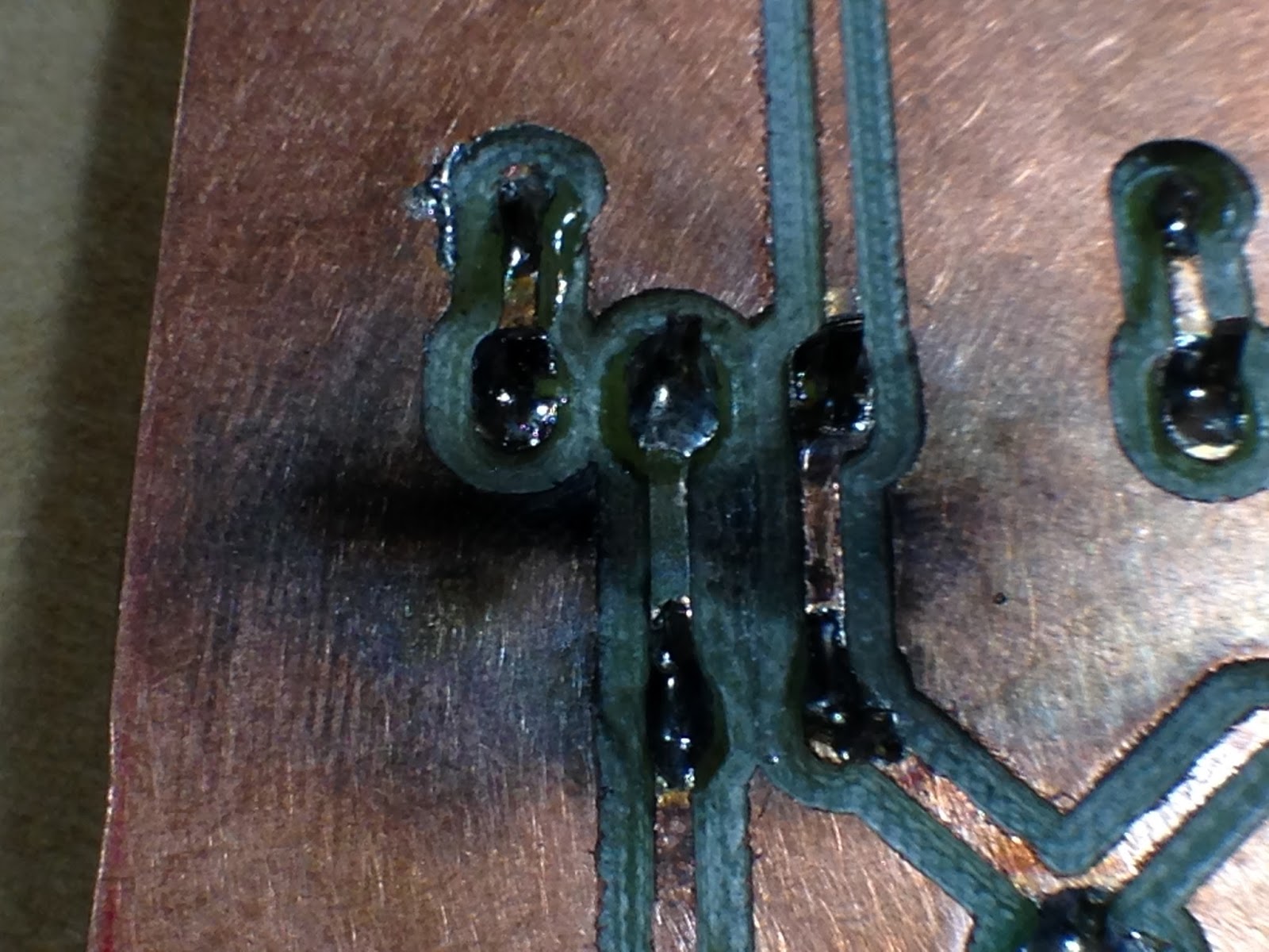
Well, for a few minutes at least and then a POP and some smoke. The MOSFET's were quite hot and looking at my new board I saw...
A trace shorted and vaporized. After desoldering all the components I determined that both MOSFET's were dead but all other components were fine.
I re-made the board on perfboard and added big heat sinks to the MOSFET's and a fan to help keep then cool. No full test yet, ramping power up slower to make sure everything is OK.
Cut copper pads from around component connections to minimize arcing.
The picture stuck in my mind - I just wanted to see one up close and in person. While on a road trip up the East Coast (early 90's) I saw a sign (it was somewhere either near or in Boston, MA) where they had some big coils that they used for a lightning display. I remember going by the museum to find that the exhibit was closed. Tesla Coils and man made lightning retreated in my mind.
Fast forward about 20 years - While working with my daughter on some basic electronics projects - make a simple electric motor using a magnet, magnet wire, a battery, paper clips and soda straws I thought why not make sparks!!!
I was really thinking about static electricity (I loved being able to shuffle across the carpet so I could reach out my finger to ZAP my brother or sister - they did the same to me of course). So, I thought why not make a Van De Graff Generator.
After building a small one, that did work, just not very well I wanted a more impressive display. A Tesla Coil seemed to be the answer, so I began my research (thinking it would only take a few weeks to build it). Well, it took a bit longer - more like 4 months research, trial and error, failures and finally success.
During my process of building the coil I was showing videos of Tesla Coils (on YouTube.com) to my daughter and we came across Tesla Coils that could play music. That just seemed so amazing, I looked into how people were able to do it. It appeared fairly complicated but I found something I might be able to do - an audio modulated Plasma Arc (or Plasma Speaker). I did try building a basic Solid State Tesla Coil (Steve Wards Mini SSTC), but I just kept blowing MOSFET's and they were expensive and I had to get them by mail order. So, I put the project on hold until I had more knowledge.
Now, I'm finally going for it and I thought exhibiting at the Southland Mini Maker Faire would be great motivation to finish it . I re-built my half H-Bridge driver board (using my CNC to mill the board). I connected everything up and it WORKED.
Well, for a few minutes at least and then a POP and some smoke. The MOSFET's were quite hot and looking at my new board I saw...
| Missing trace |
I re-made the board on perfboard and added big heat sinks to the MOSFET's and a fan to help keep then cool. No full test yet, ramping power up slower to make sure everything is OK.
| New Half H-Bridge Board |
Cut copper pads from around component connections to minimize arcing.
Monday, July 27, 2015
Chicago Southland Mini Maker Faire
I finally submitted my registration for the Chicago Southland Mini Maker Faire.
This year I'm building an audio Tesla Coil (or: audio modulated, singing Tesla Coil etc). I've built a good number of Spark Gap Tesla Coils but my attempts at building a Solid State Tesla Coil seem to result in dead MOSFET's and magic blue smoke.
Labels:
arduino,
maker faire,
music,
Tesla,
Tesla Coil
Thursday, June 25, 2015
My Hackaday Prize entry
Finally decided on a project for the Hackaday Prize. It's been going around in my head for awhile so I already have an approach and done a bunch of research into the science for this idea.
You can check it out here Stripless-bG-Measurement for Diabetes management.
Project Edge Lit Sign - PART 2
The Electronics
This part of the project took me a bit longer than I expected. I thought I had everything figured out for the design, parts and programming for the micro controller (Arduino Pro Micro) but ran into an unexpected issue that forced me to change course and use completely different hardware along with software libraries I hadn't used before. Good news is that even with the changes and learning new hardware and software the new setup is actually easier and simpler to wire up and use.
My initial electronic design for controlling RGB LED's for the sign illumination.
Parts:
Pictures of the layout:
I transferred the circuit to perf board (laid out the same as solder-less breadboard), cut and drilled out a piece of wood to mount the LED's in my box and wired in a wall wort for power.
Software library, further instructions, etc can be found at:
So, after all that work building and testing - it worked perfect but it just wasn't bright enough for the sign so I had to reboot and go a different route.
Decided to go with Neopixels - much brighter RGB LED's. Individually addressable for color and brightness, much easier to wire up - just a 3 wire connection to Arduino (Trinket or clone). Do need real basic power filter (1000uF 6.3v or higher electrolytic capacitor across power rail to filter out spikes) as well as current limit to data line (300 to 500 ohm resistor to keep current at set level).
Currently there are 2 very good libraries (that I know of) for controlling Neopixel's with an Arduino. I provided links to them as well as guides to using them below.
FastLED
Adafruit Neopixel
I'll complete this post tomorrow (Part2b) with the final electronics and code.
This part of the project took me a bit longer than I expected. I thought I had everything figured out for the design, parts and programming for the micro controller (Arduino Pro Micro) but ran into an unexpected issue that forced me to change course and use completely different hardware along with software libraries I hadn't used before. Good news is that even with the changes and learning new hardware and software the new setup is actually easier and simpler to wire up and use.
My initial electronic design for controlling RGB LED's for the sign illumination.
Parts:
- 5mm RGB Common Anode LED's
- TLC5940 shift registers
- Arduino (Nano on breadboard)
- Resistors for setting current limit
![]() |
| Wiring for TLC5940 |
I transferred the circuit to perf board (laid out the same as solder-less breadboard), cut and drilled out a piece of wood to mount the LED's in my box and wired in a wall wort for power.
| All the Parts |
| Perf Board (back side) |
| Wiring it all up |
So, after all that work building and testing - it worked perfect but it just wasn't bright enough for the sign so I had to reboot and go a different route.
Decided to go with Neopixels - much brighter RGB LED's. Individually addressable for color and brightness, much easier to wire up - just a 3 wire connection to Arduino (Trinket or clone). Do need real basic power filter (1000uF 6.3v or higher electrolytic capacitor across power rail to filter out spikes) as well as current limit to data line (300 to 500 ohm resistor to keep current at set level).
Currently there are 2 very good libraries (that I know of) for controlling Neopixel's with an Arduino. I provided links to them as well as guides to using them below.
FastLED
Adafruit Neopixel
I'll complete this post tomorrow (Part2b) with the final electronics and code.
Subscribe to:
Posts (Atom)